|
Cross charge (x-charge) laser design is rather widely known and used. A
good example of its application is technology laser LANTAN. Its schematics is
given at the figure below (cited from [1]).

The scheme of gas-discharge chamber of "LANTAN-2M" laser. 1 - the body of the
chamber, fiberglass plastic; 2 - ionization electrode; 3 - ionization
electrode terminal,; 4 - insulator (silica, glass); 5 - cathode of the main
discharge, 6 - anode of the main discharge. (The picture is cited from [1]).
Another good example is a laboratory laser designed by authors of [2]. I
think it makes sense to put its scheme here too (see the picture below).

Scheme of the pulsing ionization.
B) Discharge chamber. 1 - main electrodes (bronze); 2 - coolers (contain
water); 3 - dielectric walls of the chamber (alund ceramic, 1 mm thick).
The idea of the scheme is that the barrier discharge is responsible for the
ionization of the gas, so the main discharge can have non self sustainable form.
(Reminder: Barrier discharge is that kind of gas discharge, where the
electrodes are insulated from the plasma by a dielectric layer. Obviously this
type of the discharge can exist only when being powered by alternating or
pulsed current.)
In the more wide sense the scheme has two modes of operation:
A) The mode with self sustained discharge, preionized by a barrier discharge;
B) The mode, when the main discharge is completely incapable to self sustain
and it is fully controllable by the external ionization formed by the
barrier discharge.
In the mode A the scheme looks attractively to be applied in some TEA laser.
But in practice the multiplication ratio (the value equal to the energy
deposition of the main discharge divided by the energy deposition in the
preionizing discharge) appears to be small and degrades seriously with minor
additions of electronegative gases to the mixture, Moreover the main discharge
strongly tends to form a sliding discharge along one of the preionizing
electrodes. One can note that there exist methods of struggle those drawbacks,
but if we apply them the scheme becomes complicated, requiring precise timing
of the discharges, and still it remains very sensitive to the gas mixture
contaminations. I can say for example, that I was unable to get any lasing in
the x-charge lasers designs on air with CO2 mixtures (and even on nitrogen with
CO2) at the pressures over 250 torr.
Another interesting field of application may be found among the high
(average) power continuous wave (CW) or quasi continuous wave (QCW) lasers
working at low pressure. These lasers have more appropriate conditions for the
x-charge design. Apriori they use low pressure and helium. The helium is
unavoidable if one hopes for the decent output power. It provides the gas
mixture with the high thermal conductivity, needed for the cooling. The
pressure should be low just due to internal laser circumstances: the lower
the pressure - the higher is the upper laser level lifetime. In a certain
pressure range the emission cross section rises with the reduction of pressure
too. One and another allow us to reach the lasing threshold at the reasonable
levels of pumping, when the laser gas mixture is still at reasonable
temperature, and the laser chamber is still not molten. (This limitation has
no effect in the short pulse (TEA) systems, where the megawatts of pumping
power are on only for a few microseconds, and can not produce a sufficient
overheat. On the other hand in CW and QCW systems each kilowatt of pumping
power put the construction into heavier and heavier conditions, more and
more hard to survive.)
Since the pressure is low and the gas mixture is full of helium, there are
no principal difficulties for the use of the x-charge design. The suitable mode
is B, moreover than A mode is just inapplicable here, due to the fact that the
discharge glows continuously of for hundreds of microseconds, and these
periods of time are more than enough for the contraction of the most uniform
(at the initial stage) discharge.
Why one should seek such an exotic design for the continuous reduced pressure
laser if we have ye oldie tubular longitudinal scheme?
First of all the feeding voltage. The meter long longitudinal laser requires
almost kilowatt of power supply at 15..20 kV for a commercial tube and at over
35..40 kV for the amateur one (due to the gas contamination). And the laser
with the transverse discharge, having the width of 30 mm, promises to be
operational at 1..2 kV. It means the use of affordable microwave oven
transformer instead of the sophisticated high voltage unit. An additional
bonus will be that one can slightly increase the working pressure and thus
reduce the quality of the vacuum pumps being used, and also prolong the
lifetime of the gas mixture. Need to say that the mentioned transversal
discharge has the stability out of its distinguishing features even at
low pressures, It means that one needs some means of stabilization. Such
as sectioned electrodes with resistive ballast, or the usage of non self
sustain discharge type, exactly as it's offered here.
The last but not the least fact is that the geometry of the laser channel
in the form of narrow gap between two heat conducting planar walls is well
suited for the gas cooling. Let's for example take a common tube-shaped
laser: the ratio of the temperature difference deltaT between the center
and the wall divided by the total power Q of the uniformly distributed heat
source Q (in other words the thermal resistance of the cylindrical gas
column) does not depend to the tube diameter and is equal to:
Rt = 1/(4*pi*L*lambda)
where lambda [W/(m K)] is the heat conductivity of the gas, pi=3.14 is the
well known "pi" number, L is the length of the gas-discharge tube. (This
formula is quite easy to be derived from the basic heat conductivity law,
so there's no sense to make reference to any sources).
The independence of the thermal resistance to the diameter of the cylinder
may be comprehended from the next considerations: the area of the cooling
surface grows with the increasement of the diameter, but the distance for
the heat to pass does grow with the same rate. As the result the total
resistance does not change.
If we now fix the top allowed gas temperature Tmax, we'll get that the
top allowed energy deposition should not exceed the next value:
Qmax = (Tmax - Tout)*(4*pi*lambda)*L/(1-eff)
where Tout - is the temperature of the (outer cooled) wall, eff - the
efficiency of the laser.
The obtainable laser output will then have the next form:
Wmax = eff*Qmax = eff/(1-eff)*(Tmax - Tout)*(4*pi*lambda)*L
This relation explains the well known limitation of the (diffusion cooled)
CO2 lasers: "the output power depends only to the length of the tube, and the
factor of this dependency describes the quality of the laser, but generally
does not exceed some limiting value."
One may make the numeric estimations. First of all lets neglect the
dependency of the efficiency to the gas temperature and assume that eff = 0.1 = 10%. Then we'll postulate that the gas heat conductivity is determined
by the buffer gas only. It may be helium (lambda = 0.147 W/(m K)) or nitrogen
(lambda = 0.0315 W/(m K)) or either argon (lambda = 0.0164 W/(m K)). Lets
take that Tout = 20oC and Tmax = 200oC (the people's opinions on the Tmax differ
strongly, but here we take rather "classic" value [3]):
| buffer gas |
He |
N2 |
Ar |
| Wmax/L W/m |
37 |
8 |
4.1 |
The layout is totally different in case the active zone of the laser has the
shape of the planar plate (with thickness a, wideness b, and length L), being
cooled from both sides. From the hat conductivity law one can get:
Rt = a/(8*b*L*lambda), or Rt = a/(8*S*lambda)
where S is the area of the projection of the plate "on the top view".
Hence that energy input into the plasma will be:
Qmax = (Tmax - Tout)*(8*S*lambda)/(1-eff)/a
and the laser yield:
Wmax = eff*Qmax = (Tmax - Tout)*(8*S*lambda)*eff/(1-eff)/a
The obtained formula can be interpreted as the proportionality of the laser
output to the area of the surface being cooled. But one may go further and
divide the obtainable laser power for the planar geometry by the obtainable
laser power for the tube design:
(Tmax - Tout)*(8*S*lambda)*eff/(1-eff)/a     2*S/a   2*b*L
----------------------------------------  =  ----- = ------- = (2/pi)*(b/a)
eff/(1-eff)*(Tmax - Tout)*(4*pi*lambda)*L    pi*L    pi*L*a
I.e. the laser, having its active medium in a shape of thin planar layer,
allows to get power from the unit of length greater by (2/pi)*(b/a) times than
the one, obtainable from the common pipe-like laser.
The (2/pi) factor essentially describes the difference between planar and
cylindrical shapes in the relation to the heat conductivity, and the (a/b)
factor (also named as "aspect ratio") describes the elongations of the
laser channel cross section.
For example if the thickness of the plasma column is 3 mm and the wideness
is 3 cm, the aspect ratio will be equal to ten, and this tube will allow 6.3
times more power from the unit of length than the common cylindrical one. E.g.
a meter long tube will allow to get 230 W of power in the contrast to 37 W
from the common one. (Of course if other sources of losses won't interfere)
One may comprehend the nature of this gain in the next way. Let's assume
that we want a huge power from the unit of the laser length, but for some
reason we have to stick to the cylindrical geometry. The readily coming solution
is to take N laser tubes and to put it into one harness in parallel. The batch
of tubes not necessary must be three dimensional. Lets put the tubes on the
table top tightly one near another. The next step is to eliminate the walls
between the adjacent tubes. We'll loose some some cooling (which otherwise
would take place on that walls) but we will gain the integrity of the laser
beam. Maybe it will have an uncommon shape (rectangular section) but still
it will be the single beam, coherent to itself. On the contrary in case of
N tubes we would have N independent beams with all related problems in
focusing them into one point.
Trust me, I had no intention to bother anyone with considerations and
derivations, but it was necessary to point out the essence, for one to
understand the reasons forcing to test the lasers of uncommon shapes. Now
this is done and we could proceed to the results of the tests, but one
more notice before this. I should say at the very beginning that the task
of "outperforming the commercial lasers" is not considered seriously here.
Indeed I got used to obtain efficiencies being one order of magnitude lower
than ones of the commercial grade devices. Since that I would be glad if
my tubes (abusing the benefits of the planar design) could even approach to
the parameters of the commercial cylindrical lasers.
1. Laser cells
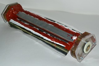
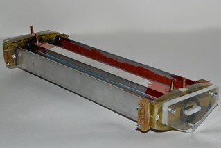
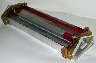
The idea and scheme of the laser cell are more than clear when looking at
the pictures given above. Here we'll stop only on the materials and the
specialties of the assemblage.
The dielectric walls of the cells were made of inorganic (window grade) glass,
2 mm thick. Such a glass is affordable from some frames for photos, or either
it can sometimes be ordered in glass shops. In the latter case it makes things
much easier, because one can also order the appropriate cutting.
The smaller photo frames can contain some 1 mm thick glass, but their size
is less than 200 mm, and if we used such a glass, we'd have to make segmented
walls, hard to be sealed vacuum tight.
The glass walls are 400 mm long (made of photo frame glass 400 x 300). The
width of the glass is determined from the sizes of the electrodes and the value
of the spacing between them.
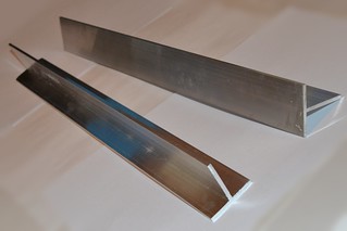
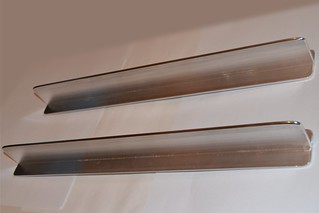
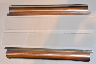
Two different types of electrodes have been made. The first pair of
electrodes is made of T-shaped aluminium extrusion directly. Another pair of
electrodes has more sophisticated design (initially intended to reduce the
total size of the cell). Both types of the electrodes have the thickness of
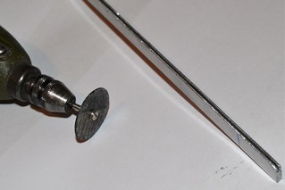
3 mm. Of course all edges and angles were rounded, and the working surface
was polished. The inter electrode spacing is 30 mm (the aspect ratio of 1:10).
With the sizes of the active area at 3 x 30 x 400 mm with commercial quality
of the gases and assemblage one could hope to get about 80 Watts of output, but
I expect only 8..10 W.
The vacuum cell, having the wall 30 x 50 cm, feels the atmospheric pressure
of 120 kg. It looks like too much for the 2 mm thick glass. Therefore the glass
walls of the cell are supported by some aluminium parts, having been glued
upon the walls. These parts play the role of coolers and at the same time serve
as the electrodes of the external ionization.
The coolers-ionizers are made of rectangular aluminium tubes, 25 x 10 mm
cross sectioned, 380 mm long. The ends of the tubes are sealed off. It is
supposed that at some point they can be filled with cooling water, provided
that the cell could live long enough to achieve the mentioned point of
necessity. The sharp edges and angles are rounded as usual. The coolers-ionizers are glued to the glass walls using a silicone sealant, in the hope
that it will provide some freedom for the parts to move, and thereby, will
reduce the tension, arising due to the different heat expansion of the glass
and aluminium.
The endpieces. Somebody among the great physicists has said: "If the God has
created the volume, the Devil has created the surface." Being applied to our
problems it means that "Devil has created the ends". It is almost easy to seal
off the joint of the electrodes with the glass walls, but You will be very
unhappy with the endpieces.
The cells are meant to be sealed with silicone caulk, and thus one should
choose the material for the endpieces more carefully. The silicone sticks to
the glass well. It is also good for aluminium/ However the endpieces are hard
to be made as a single piece of inorganic glass. And metals are bad choice
too, due to the possibility to shorten the discharge. On the other hand organic
glass, polystyrene, PVC or polyethylene are prone to detach easily when glued
with silicone. Fortunately it was found out that epoxy molds are very
compatible with silicone, so the endpieces were made of epoxy resin.
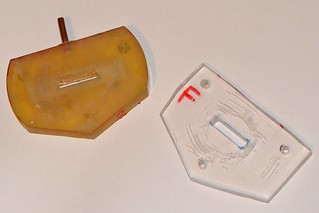
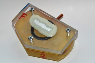
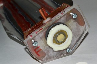
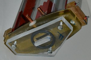
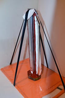
The endpieces and mirror mounts have an unusual shape. It is due to the
specific shape of the laser cell and channel. As it was said above the
endpieces are made of epoxy resin and the mirror mounts are made of organic
glass 10 mm thick.
Finally all this husbandry was glued up into a complete construction.
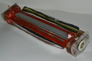
Interlude 1. Technological. VACUUM TIGHT SEALING.
↑
The "adult" technique knows only three ways of permanent vacuum sealing:
those are welding, soldering and brazing. All types of flanges and rubber
gaskets are apriori considered as leaking and aging. The question is only
at which rate.
Welding brazing and soldering require the device to be assembled in the
glass or metal vessel. The first requires a hardcore glassworking. The second
not only requires machining, but also rises problems with electric strength.
Both variants require some solution to entry the electric current into the
sealed volume. It may be metal-ceramic terminals, glass-metal solds and so on.
All those things are expensive, rare and hard to make at home.
A DIY'er has to rely upon temporary solution an reconcile to some leaking.
In this area the choice is quite wider. One may use glues, plastics, sealants
etc. The most known and widely used ways of sealing are the next three ones:
- Sealing with a hot glue ("glue-gun", low molecular polyethylene)
- Filling with an epoxy resin
- Filling with a silicone caulk.
One can also remind that there also exist sealing of rubber parts with a
rubber glue and sealing metal parts with tin, but those methods are rarely
met in practice.
• Hot glue works best with "fat" plastics: polyethylene, polypropylene, PVC,
etc. The fluoroplastic is a sad exclusion. The hot glue works good also with
metals (aluminium, copper, steel, including the galvanized one). However in
order to get good results with metals one must literally blanch them with
the hot glue, baking it in by some torch or a heat gun. Gluing the inorganic
or organic glasses gives good results too. In case of inorganic glass one
should bake in the hot glue too. Be careful in this case for not to crack
the glass. Gluing of epoxy molds or textolite is also good.
Being a fat hydrocarbon the low molecular polyethylene dissolves grease,
and thus is tolerant to some grease contamination. In the reasonable amounts
of course. Some oil dipped parts are very unlikely to be able to be glued
together.
The hot glue is good for vacuum or low aggressive gases. It can work
underwater. Much worse it endures alcohols and acetone (flakes off in several
weeks or even days). Petrol, kerosene and gear oil do dissolve the hot glue.
(Not instantly, but for a long time operation with these liquids the hot glue
is inappropriate.)
It develops brittleness under the sun rays or even after a long storage.
Due to the appearing fractures the lasers, having been sealed off by the hot
glue, loose the vacuum tightness in two-three years.
In the home conditions the hot glue is exclusively good for sealing. Small
vessels, several cubic centimeters in volume, can be sealed to have leaks less
than 100 torr per year. However it usually requires several attempts.
When heated it is able to self cure the leaks. If the seam does not allow
the hot glue to get into the vessel, one can evacuate the vessel and heat
the seam. In this case the hot glue can self cure small leaks.
• Epoxy resin. Sticks excellently to itself or to materials based on it
(textolites, epoxy plastics). Not able to glue "fat" plastics (polyethylene,
mylar, PVC, etc). Poorly holds the inorganic glass, even if its surface
was grinded. Better, but still poorly, glues the organic glass. The results
with metals depend strongly to the type of the metal being glued and to the
type of the epoxy resin (look at the writings on its box if it is intended
to glue the chosen metal) and to the condition of the surface. Before gluing
the metal surface should be grinded or, better, grooved. Gluing the mirror like
polished metals is the way to fail.
The most special property of the epoxy resin is that it is able (on the contrary to the hot glue or silicone) to stick to zinc selenide parts vacuum tightly. So if You are using selenide mirrors or window_s You may have to use the intermediate parts made of epoxy or textolite. The ZnSe things will then be glued to those intermediate parts by means of epoxy resin and the intermediate parts in their own turn will be glued to the rest of the construction by any other sealant of Your choice.
Epoxy resin is intolerant to grease. In fact most of failures are oftenly
explained as the affect of the contamination. Indeed the grease is the best
excuse for the resin manufacturers. From the practice of glass silvering we
know, that in order to completely degrease the surface one should boil it
for several hours in a concentrated nitric acid. Rare parts are able to
endure that so the excuse works almost always.
Epoxy resin is capable to hold vacuum and gases. Most of the epoxy resins
(excluding the ones, specially intended for wet conditions) are prone to flake
off when used in water or high humidity. Even more fast the flaking takes
place under the action of alcohols. Epoxy resins tend to soften when exposed
to acetone for a long time (several days). This fact can be used to disassemble
the connections, having been glued with epoxy. Epoxy resins are usually durable
to the action of gasoline and mineral oils. However no warranties here.
The connections, having been glued by epoxy resins have exclusively long
lifetime. Most of them continue to work even after 10 years of use. However
the seam is rather brittle. And if it is exposed to thermomechanical loads or
bendings, its lifetime shortens seriously.
My personal experience says that the results of epoxy resins usage for the
tasks of vacuum tight sealings give average results. I've heard about some
commercial He-Ne (or even argon) lasers, where the mirrors were sealed with
epoxy. Evidently they use some very exotic resin or very special gluing
technology. On my memory the best epoxy glued things had leakages of several
torrs a day. It is understandable that there's no sense to speak about years.
The seam is hard, brittle and is not capable for self-curing.
• Silicone caulk. Ideally suitable for gluing inorganic glass. Also suits
good for aluminium. Completely incapable to stick to the "fat" plastics
(polyethylene, mylar, PVC, etc). With other materials it gives unpredictable
(and usually bad) results. For example silicone caulk flakes happily from
organic glasses. Recently I've been able to discover that the adhesion of
silicone to organic glass (and many other materials) can be highly improved
if the organic glass surface was painted by a rhodamine marker before gluing
up. It is still unclear whether the rhodamine itself is responsible for the
phenomenon, or either the surface active additives do that. It also was
found out that silicone sticks well to epoxy molds. However it is still
unclear how long such a connection will live. Silicone caulk (as like as
epoxy resin) completely hates grease. So the surfaces to be connected must
be cleaned thoroughfully.
Silicone is durable to water, vacuum and gases. Longer than other (known to
me) sealants endures alcohols and acetone (however it finally fails too).
Automotive silicones are durable to gasoline and oils.
Silicone seam has usually excellent lifetime. It can keep integrity for
tens of years, A fly in the ointment is that it keeps its integrity all by
itself. Apart from the parts that've been sealed. Silicone is prone to flake
off anything but inorganic glass, With other materials the moment, when it
decides to do it, is unpredictable. Anyways none of my lasers (the ones having
been sealed with silicone) have stayed vacuum tight longer than a year.
In the short time perspective silicone gives an illusion of an ideal thing
for sealing. The vessels, having been sealed with silicone, leak exclusively
slow (it is easy to get less than 1 torr a day). With some experience one
can easily succeed in vacuum tight sealing from the first attempt.
Silicone has a property to self-cure the leaks. It works in the next way:
there is a little hole somewhere, and there is a silicone snot above it.
Certainly when the pressure is lowered the snot is sucked to the hole and
shuts it. Not always this is for good. Because if You shake the laser all
leaks can open once again. And it is double pain to hunt for something
unstable.
Generally silicone is good for the projects of the "make-work-dispose" style.
Only one fact complicates everything: the silicone cures for indecently long
time. Thick seams with restricted air access can cure for several weeks. Even
longer they can contaminate atmosphere in the laser by their fumes.
And finally some general recommendations:
- The number of places for sealing should be as low as possible.
- The seams should be as short as possible.
- The seams should have a simple and closed shape.
Examples:
- A mirror on one of the ends of laser. Or a looking window on its side. The
total length of the seam is small and it has a shape of closed ring. This
sealing is usually easy and produces good results.
- A glued up box having a shape of a rectangular parallelepiped. The total
length of the seams is huge. The corners of the box are the places, where
three seams meat each other - too complicated shape. And also the shape
of the seams is open (one usually can not glue all the box in one action).
As the result this is ne of the most complicated designs to be sealed off.
There's low probability of the success. The leaks are usually situated in
the corners.
- Planar (low inductance) terminals of nitrogen lasers, The seam is long,
but has a simple shape. In some designs it can also be closed. Result:
the terminals are usually easy to seal and provide much less problems than
the endpieces.
2. Power Supply Unit
The power supply unit is made following the KISS principle ("keep it simple").
It consists of:
- microwave oven transformer
- electronic transformer for halogen lamps (ye olde Feron 250 W rated)
- two ignition coils with closed core (E - shaped).
- a head from some small milliammeter
- a bunch of diodes for assemblage of a diode stack (note that here's no need
to rectify the voltage from the ignition coils, it is used for ionizing and
should stay alternating)
There was also used a ballast resistor in the "low voltage" feeding circuit.
There are also some kilowatt rated halogen lamps in series with mains cords -
the standard precaution for works with high power devices fed by mains. One can
use fuse here, but it would bother to replace them each time.
WARNING! It should be mentioned that the output ratings of the microwave oven transformer are similar to ones of the electric current used in the electric arm chairs. The only difference is that electric arm chairs use direct current, while here we have an alternating one. However this difference will mean nothing if one touches the output terminals.
REMEMBER! MICROWAVE OVEN TRANSFORMERS ARE LETHAL!
Yes, lethal. And still handy, robust, cheap and affordable when we speak
about a source rated to several kilovolts and several hundreds of milliamperes.
The scheme of connections is the next:
                                double horned
                                  ignition +-------+
            +-------------------+   coil   |       |
   o--------|         )|        |---o--- |(        |  laser channel
  ~ 220 V   |  Feron  )|( 16    |       )|(      =====
            |  250 W  )|( turns |       )|(   +--)   (--+
   o--------|         )|        |---o--- |(   |  =====  |
            +-------------------+          |  |    |    |
                                           +--)----+    |
  microwave                       Rb          |         |
    oven           8 x HER308     6k8         | Cp 4 nf |
 transformer   ---|>|--...--|>|--/\/\/--------+---||----+
   4kV peak ||(                                         |
   o------- ||(                                         |
           )||(                                         |
           )||(                                         |
   o------- ||(     0..100 mA                           |
            ||(        /                                |
               ------(mA)-------------------------------+
                     /
The microwave oven transformer has the output of 4 kv peak. (This sample has
the said voltage. Generally I've seen ones giving from 2.8 kv to 4.3 kV.)
A shunt was designed specially for the milliammeter head to make its limit
of measurement to be 100 mA (constant current). The resistance of the shunt
appeared to be 2 Ohms. Here's no smoothing, at least for now, since in 50Hz
pulsed mode we have lower average power and hence can avoid water.
At first there was no Cp capacitors. Those capacitors, connected in parallel
with the laser cell - so called "peak capacitors", or shortly "peakers". Later
it was found, however, that connection of the peakers to the laser cell allows
to rise the top current, at which there's still no arcing (surge current).
Initially the ignition coil was also single. However the tests have shown
a serious deficiency of the ionization. Increasing the ionization voltage was
not acceptable due to breakdowns in the laser cell, so it was decided to reduce
the series resistance of the transformer (ignition coil). The simplest way to
do this is to connect two identical ignition coils in parallel. There were
doubts if the coils would agree to operate in this mode, but the tests were
successful (see below in the results section).
The general view of the power supply unit with and without the top plate
with the laser cell installed are shown below.
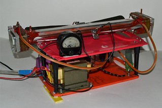
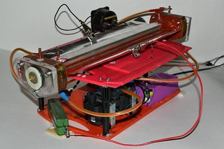
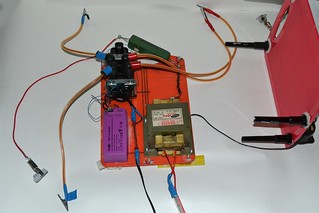
Later it was understood that at the design pressures the laser was unable to
reach threshold. And for the lower pressures the voltage of 4 kv microwave oven
transformer is excessive. There could be one rated to 2.8 kv, but who knew it
beforehand? After this the microwave oven transformer was connected not
directly to the mains but through a variac. This provides an ability to finely
tune the voltage and to approach smoothly to the surge current (the limit of
arc formation.)
3. The Results
30.01.2017
The first of the laser cells (the one having foil terminals) was installed
onto the initial variant of the power supply unit (the one with the single
ignition coil, without voltage regulation by variac, and without peaking
capacitors).
The gas discharge in the cell was tested. During the tests the cell was
filled by welding grade argon at different pressures.
- At argon pressures above 2.8"Hg (inches of mercury) and without any
external ionization, the output voltage of the microwave transformer is
just not enough to cause the breakdown in the cell. The current is zero.
- When the external ionizer is on, there appears a current in the "low
voltage" part of the circuit. By gradual decreasing of the pressure and
smooth approaching to the breakdown threshold (2.8"Hg) one can (rather
reliably) achieve currents of two divisions of the milliammeter scale
(10 mA).
- With the increasement of the pressure the current drops rapidly and
it becomes immeasurably small already at 3.5"Hg.
- When reducing the pressure, somewhere between 2.5 and 2.7 inches of s
mercury the current suddenly jumps (up to 25-40 mA) and the discharge
contracts. One can note, however, that here the applied voltage exceeds
the one of the cell breakdown.
- In parallel to the milliammeter (shunt resistance 2 Ohm) an
oscilloscope was attached. The oscillograms show that the current through
the laser cell is formed by series of bell-shaped pulses with their tops
being flattened slightly. The duration of the pulses is 3.5-4.5 ms at the
half height, the repetition frequency is 50 Hz (period of 20 ms). The
amplitude of the current pulses is up to 60 mA, when the milliammeter
shows two divisions.
- Addition of two peaking capacitors (2 pcs of Murata 2 nf x 40 kv doorknob
capacitors, connected with wide stripes to make the inductance low) does not
change anything by itself, but allows to obtain 1.5-2 times greater current.
- In the uniform glow mode (current as measured by milliammeter at 10 mA)
the cell stays almost cool. It means if I was able to get lasing, I could do
it without cooling water.
- The is no success in current increasement. Either we have that we have,
or the discharge drops to arcing. And this is in the inert gas, where the
lifetime of free electrons should be long, and the multiplication ratio should
be top most.
31.01.2017
The cell was equipped with mirrors. The rear one is the rearview automotive
one. Aluminium on glass, concave with 2 m radius. The front mirror is
commercial one, ZnSe coated by dielectric. Plano, 10 mm in diameter. Reflection
is 94% (I have no larger mirrors with such a high reflection).
The cell was filled with mixture CO2:N2:He = 2:3:15 (or either 0.4:0.6:3,
the share of molecular gases was one third).
The first thing that was noted - the drop of current. If one could achieve
average current of 10 mA with argon or argon mixed with 10% of nitrogen, then
here one could get only 5 mA without surging to arcing. (Here I use the term "average" current to designate the current as shown by milliammeter. If
the shape factor was kept unchanged it means only 30 mA of peak current). Need
to say that the helium was taken from a party balloon with unknown storage time
in the shop. The nitrogen was welding grade, but it stood a long storage in
an intermediate vessel (PVC ball). CO2, as usual, was taken from a Crossman's
cartridge, and the quality of these cartridges does not grow year to year.
There were some runs on CO2:N2 = 2:3 mixture. With this mixture there was
no range of operation at all. At higher pressures the current is immeasurable
(less than 1 mA avg) and when trying to lower the pressure it immediately goes
to arcing.
Nevertheless the laser was aligned and got a run. No lasing was observed.
Neither in the mode of low current (I=5 mA avg) nor in the mode with arcing
(I=40 mA avg).
In attempts of increasement of the preionization power the number of turns was
increased in the winding that feeds the ignition coil (inside the Feron
electronic transformer). As the result the voltage caused a breakdown of
silicone near the cell endings. The charred silicone was removed and the
remaining silicone was covered with epoxy.
02.02.2017
Ionization voltage was returned to the previous level. And to increase the
ionization power the second ignition coil was installed in parallel with the
first one. Also the wires (the ones connecting ignition coils with the
ionization electrodes) were replaced. Previously the automotive type high
voltage wires were used. Their drawback is that they are designed specially
to suppress radio interference and thereby can suppress the most useful
part of our ionization current too. At their place just common copper wires
were installed, that should reduce RF losses. Ballast resistor was also
reduced (from 6.8 kOhm to 3.4 kOhm).
Test run with argon:N2 = 1:5 mixture:
- The glow inside the cell became much brighter. And not only the glow
from the ionization source became brighter, but the brightness increasement
given by turning on the main current became much more prominent.
- Average current (the top achievable without dropping to arcing) stayed
unchanged. It was 10 mA and it remains 10 mA. It is especially incomprehensible
when taking into account the increased glow.
- The corner of the laser cell (silicone sealant between the electrodes
and endpieces) was charred again. After this an attempt was made to clean the
ill place ant to fill it with epoxy. However it is clear that the error is in
the design/ One should leave much greater reserve between the cooling - ionizing
parts and the endpieces. Generally the cell should be redesigned.
- With a variac one can succeed in using the cell at higher vacuum (than
the previous 3 inches of mercury) with corresponding reduction of feeding
voltage. With decreasing of the pressure the allowable current decreases too
but slower than the pressure. At one inch of mercury one could get to
somewhere between 5 mA avg and 10 mA avg without arcing.
06.02.17
The cell with the foil terminals is now dead. the breakdown of the silicone
near the endpieces appeared to be fatal. In attempts to increase current and
drive the cell to lasing its glass wall was overheated and cracked.
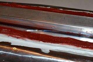
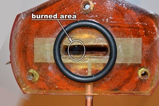
The cell with T-shaped terminals (the one with its electrodes being made
directly of T-shaped aluminium extrusion) has agreed to lase. With the mixture
of CO2:N2:He = 2:3:15 havin been mixed 31.01.2017. Resonator is also the same.
Rear mirror is automotive rear view mirror (washed out from the protective
paint), aluminium on glass, concave R=2 m, the front one is ZnSe plano,
dielectric coated, ro = 94%, 10 mm in diameter.
The measured output power was 6 mV by the readings on the homemade Peltier
calorimeter. Calibration of the calorimeter was checked once again but it
constantly gives 6.4 mW/mV. It means the laser gave 38 mW of output.
(Note that the integration spacing was 30 and the 10 mm mirror intercepts
only one third of the laser channel width).
To increase the area of the resonator a hybrid front mirror was made. In a
glass concave mirror (automotive one, R=2 m, aluminium coated) a 10 mm hole
was drilled and then the hole was covered by the mentioned above ZnSe 10 mm
94% mirror. Care was taken to keep alignment between the concave glass part
of the hybrid mirror and its ZnSe part.
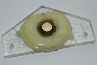
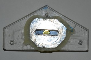
With the same gas mixture and with the new mirror the maximum output was
12.5 mV (80 mW), but the result is not directly comparable, because here
the laser was allowed to go deeper into the mode with arcing.
The results of observations (it hardly can be called as "measurements"):
- The pressure optimum is sharp and lies between 1.1 and 1.2 inches of mercury.
At 1 inch and at 1.5 inches the output drops to one half of the optimal one.
At 0.5 inch and below and at 2 inches and above no lasing was attained.
- That lasing threshold is about 10 ma (by the indications of the
milliammeter) and it depends weakly to the pressure (in the range of
pressures, where the lasing was attainable). The threshold of arcing lies
at the same 10 mA when the pressure is optimal. I.e. when completely
without sparks there's no lasing too.
- Going further into the area with arcing gives the optimal output at the
average current of 20 mA. Further addition of current leads only to drop of power.
The arm of the milliammeter here jumps strongly (due to the random arcing)
so the correct readings are impossible. The variac appears to be set to
100..110 V here.
The highest laser output is when the arc is "running" (randomly appears in
different places of the laser channel). When the arc sticks to a certain
place on the electrodes, the laser output drops significantly.
- The cell heats strongly. The tests were made without cooling water, and
in these conditions the coolers become hot to touch (about 40oC) in less
than a minute of operation.
DONT TOUCH ANY PART OF THE LASER UNTIL ALL THE
VOLTAGES ARE TURNED OFF!!!
To the end of the series of the tests something went wrong and the mode of "running arc" became unattainable. The output power of 12 mW became
unattainable too. The arc has stuck to a point on the electrodes and refuses
to leave the place. The top power in this mode was 4.5 mV only (28.8 mW).
07.02.2017
To understand further reading we should discuss the structure of the laser
cells in more details. The schematic section of cells in ASCII graphics is
shown below:
                  delta
           25 mm  2.5 mm
     |<>|<------>|<>|
     |   ________   |
     |  [________]  |
   ====================
 ////)              (////
   ====================
     |  [________]  |
     |              |
     |    30 mm     |
     |<------------>|
For things to be more clear I place here a picture too (however the bad thing
with the picture is that it is stored separately from the text file, and when
You've downloaded the file for the offline reading at the very moment it may
appear to be lost.)

The gap, designated as "delta" on the drawings has appeared here not
accidentally. Its presence or absence affects the discharge shape strongly. In
the pulsed lasers (not actually TEA but similar) the introduction of this gap
allows to suppress sliding discharges along the ionizing electrodes, and thus
to reach the lasing action at pressures up to 250 torr with mixtures of air
with CO2. Without this gap the top pressure, at which the volumetric discharge
still exists in this design in oxygen-containing mixtures, was below 40 torr.
When there was a hope to get a working laser at higher pressures this gap
was excusable. But now, when one can see that the laser can not reach threshold
even at 50 torr this gap may harm, because it leaves an area of non ionized gas
that can cause improper breakdown when under the main voltage.
The gaps were covered with aluminium foil (put it above the glass of course).
The behavior of the system has changed. Previously the top pressure at which
the uniform glow was attainable was 3 inches of mercury, and the attainable
current was almost independent to the pressure and was equal to 10 mA (by
the milliammeter gauge indications). Now the limiting current depends to the
pressure an is equal to (with mixture CO2:N2:He = 2:3:15)
| P |
Imax |
| 0.5"Hg |
5 mA |
| 1.0"Hg |
10 mA |
| 1.4"Hg |
15 mA |
| 1.5"Hg |
10 mA |
| 1.6"Hg |
5 mA |
Above 1.6 inches of mercury there was no success in obtaining the uniform
glow.
Tests for the lasing (resonator is the same as was in the record of 06.02.17):
- The dependence of the output to the pressure has very sharp maximum. When we
approach the top pressure, at which the uniform glow is still obtainable, the
output power grows rapidly. When the arcing appears the power drops by 2-3
times, but the lasing is still present.
- Somewhere a bit below 1.5 inches of mercury (probably 1.45"Hg - I cannot say
precisely due to the lack of the vacuometer precision) the laser yielded 30 mV
by the indications of the calorimeter (192 mW). When its output is focused
by a lens (F=75 mm) the laser rapidly burns carbon paper and it is able to
ignite a match (even when it is hold by hands - not very firm ones).
09.02.2017
The output mirror (hybrid one) was replaced by another planar ZnSe mirror
having reflectance of 85% and diameter 15 mm. It was installed alone - without any attempt to make another hybrid mirror.
At 1.45 inches of mercury the laser with this mirror is unable to reach the
threshold. The top pressure, where the threshold is attainable is 1.1..1.2"Hg.
The maximal power is 12 mV = 77 mW; the optimal pressure is 0.9..1"Hg.
It is interesting that the dependence of the power to the pressure has lost
its sharpness and its maximum has shifted to the lower pressures. The maximum
is noticeably lower than the limit of the discharge stability.
Then the rear mirror was replaced. A planar glass mirror coated with
aluminium was installed. It is an old (ab)used mirror from a nitrogen laser
that has noticeably darkened due to aging. The resulting laser power has
dropped further on. It became 6..8 mV = 38..51 mW. Optimal pressure became
even lower and the maximum itself became even more soft.
What do the words "optimal pressure became even lower" mean? In fact when
the 94% hybrid mirror was replaced by 85% simple one the laser could not reach
the threshold in the area of stable discharge (15 mA) but still could lase
in the area of the discharge with some arcing (20 mA). With lowering the
pressure one could return the threshold to the area of the stable discharge,
but with the corresponding lowering of the output.
When the front mirror was
replaced too, the threshold raised once again and could not be returned to
the area of stable discharge by any changes of pressure. (Need to notice that
the current border of the stable discharge shifts to lower values with the
reduction of the pressure.) However the one could still move the threshold
into an area, where the discharge contains some arcing (<20 mA). Of course it
caused further drop of the output.
Also need to notice that the border of the discharge stability shifts with
time. It is the lowest at the first turn on of the laser. It is about 10 mA.
After some baking of the electrodes the border moves somewhere to 15 mA,
sometimes it can reach 20 mA. If there appear a bright arc, it burns a spot
on the surface of the electrodes and the border of stability drops to 10 mA
again. Then the cycle repeats. (Here always we speak about the "average"
current as indicated by milliammeter).
Further on an idea to remove peaking capacitors had stroke my head. The
achievable current (without falling to arcing) has decreased strongly (to
about 7 mA) and refuses to rise back. Of course no lasing is here.
I.e. the peakers are essential for the laser operation. It may be due to
they form a relaxation oscillator together with the ballast resistor and
with the laser channel itself. Its frequency should be about 73 kHz, so
the laser channel is actually fed by RF current.
Then an assembly of four K15-4 capacitors (4.7 nF x 12 kV each) was placed
instead of the peaking Murata's. The area of the stable discharge just
disappeared. When using the variac to increase the voltage, initially there
is no discharge at all and then suddenly there appears white spark in the cell.
The spark is fat, strong and has a hearable sound.
Then the K15-4 assembly was removed, and a single Murata (2nF) was placed in.
The area of the stable discharge has reappeared. The lasing was even got there
(4..6 mV) but the things were much worse than with two Murata's.
Then in parallel with the laser electrodes three Murata's were placed
(1/RC = 49 kHz). The power became 21 mV = 134 mW. (One can suppose that if
we return the previous mirrors there will be 400..500 mW, but it usually
does not work in such a way).
The question on the optimal value of the peaking capacitors Cp should be
studied further. It also has a sense to check how the laser will react to the
capacitors of different types. E.g. to the single K15-4. Or to mylar film
rolled K73-13.
13.02.2017
The results with different mirrors.
With the mixture of CO2:N2:He = 2:2:15
- With the front mirror, plano, 85% reflectance; with the rear mirror plano,
aluminium coated glass; and with 3 x 2 nF as the peakers the laser as it was
already written above reaches 21 mV (134 mW)
- With hybrid mirror as the front one (a hole in the center of Al coated glass
concave mirror, enclosed with plano ZnSe 94% mirror); with the back mirror
plano, Al coated glass; and with 3 x 2 nf peaker the laser yields 25 mV
( 160 mW)
- With the hybrid mirror as the front one and with rear mirror concave, Al
coated glass, and with 2 x 2 nf as the peaker the laser yields 30 mV (192 mW).
All concave mirror were spherical with the curvature radius of 2 meters.
Further on (in the resonator having the front hybrid mirror and the rear one
concave) the next gas mixtures were tested:
- CO2:N2 = 1:2
- the highest pressure, at which the lasing was observed 0.6"Hg
- the optimal pressure 0.5"Hg
- the highest current (by milliammeter) achievable without
dropping to arcing: 3 divisions (15 mA)
- threshold current (by milliammeter) a bit less than 3 divisions
(~14 mA)
- top registered output power 6.4 mV (40 mW).
- CO2:N2:Ar = 1:2:6
- the highest pressure, at which the lasing was observed 1.5"Hg
- the optimal pressure 1.3"Hg
- the highest current (by milliammeter) achievable without
dropping to arcing: 4 divisions (20 mA)
- threshold current (by milliammeter) 2.5 divisions (~12.5 mA)
- top registered output power 25 mV (160 mW)
A tiny droplet of xylene was added into the tyre, that contains the
mixture. Gases then were stirred vigorously. As the result the surge
current and the lasing yield became lower (3 divisions and 16 mV
correspondently).
- CO2:N2:Ar = 1:3:6
- the highest pressure, at which the lasing was observed 1.4"Hg
- the optimal pressure 1.4"Hg
- the highest current (by milliammeter) achievable without
dropping to arcing: 3.5 divisions (17.5 mA)
- threshold current (by milliammeter) 2.5 divisions (~12.5 mA)
- top registered output power 37 mV (236 mW)
- CO2:N2:He = 1:2:6
- the highest pressure, at which the lasing was observed 1.5"Hg
- the optimal pressure 1.3"Hg
- the highest current (by milliammeter) achievable without
dropping to arcing: 4 divisions (20 mA)
- threshold current (by milliammeter) 2 divisions (~10 mA)
- top registered output power 25 mV (160 mW)
Hardly comprehendible why increasement of nitrogen to CO2 ratio
has caused output drop when with helium and caused power rise when with
argon. Is it the native properties of the mixtures or just the impurity
of the experiment. (Helium was stored in automotive tyre from the may
of the previous year. By the way, if stored in party balloon it would be lost and dead ten times already. And, judging by the discharge current and
lasing, the tyre did really contain helium after all this time. However
its purity might be low.)
There also were runs (on CO2:N2:Ar = 1:2:6 mixture, after xylene addition)
in gas - static mode. The lasing does probably exist at the first moment
after turning on, but no continuous lasing was observed.
Need to say that all previous runs with lasing were in the slow gas flow
mode (somewhere at 0.1 - 0.3 liter*bar per minute). To achieve this, the
exhaust pipe (the one that goes to the vacuum pump) is clamped slightly.
The gas/vacuum valve on the incoming pipe (the one connecting the laser cell
with the tyre) is to be set to a position that provides the proper pressure
(e.g. at 1.5 inches of mercury column). After this one may turn the ionizer on,
and then turn on the power of the main discharge.
Having read in articles and web-reports how fast do the low pressure
continuous lasers burn out the gas mixture, I have never (until now) tried to
get the lasing in a gas static mode. Ant it is very expectable, that the
first try is fail. (Naturally one could use gas regenerators, special gas
mixture and special materials for the tube, but I had neither desire to do
that, nor the possibilities.)
The web-report genre is rather free and one of its drawbacks is that one
usually needs to read tons of unnecessary info in order to understand what
was meant in one or another place. However need to note that the guides are
best to be read as the entirely whole too. Sometimes somebody, having read
three paragraphs, thinks that he've understood anything and rushes to
production. But no - it does not work. And the one(body) becomes frustrated
and rings all over the mail and internet... And this is when he(she) could
just read the guide a bit further, or a bit more attentively, or a bit more
thoughtfully, or a bit more patiently and get all the answers.
Back from lyrics... Another test run was with CO2:N2:He = 1:2:6 mixture
and another output coupler. This one has diameter 25 mm (ZnSe, dielectric
coated) and reflection of 75% or 50% (The marks on it have disappeared
in the process of epoxy-mounting. Occasionally i will measure its reflectance
and write down here). The laser haven't reached threshold with this mirror
at all.
14.02.2017
Turning On the Brains.
Finally the top power, that have been achieved to the moment, is 236 mW.
With taking into account the fact that the resonator does possibly gather
the light poorly (say one half) and taking into account the duty cycle (suppose
that it was one fifth) we'll get that this laser can give 236 mW x 5 x 2 = 2.36 W in continuous mode.
It have already noted above about the caution to be taken when making
such an estimations. For example considering the light gathering by the
resonator - all affordable mirrors and their combinations have already been
checked (plano-plano, plano-concave, concave-plano, concave-concave/hybrid)
and I already use the best one (concave-concave/hybrid). So here's a little
hope to move forward in this area. Or I should try to install mirrors
directly into the waveguide? The reference waveguide parameter B of the mirror
set up is B = pi*w^2/wavelength, where wavelength = 10.6e-6 m,
w = 0.7*(a/2) = 0.7*1.5e-3 m
- for the planar channel, pi = 3.14...
Substituting the values we get B = 0.326 m. And the condition of low losses
due to modes mismatch, which has the form [3]: h < B/10, where h - is the
distance from the waveguide end to the mirror. We can see that this condition
is fulfilled, because in the current design h is less than 2 cm.
On the other hand we can remember a pocket-sized-lamp-pumped-dye-laser,
where this condition was fulfilled with even more warranty and still the closer
mirrors were to the capillary the better it worked. So in reality here we have
the possibilities unknown...
Coming from the pulsed power to the continuous does promise five times up,
but in reality we can meet gas burning out, or developing of the misalignment
due to overheat. And the promised five can turn out to be three or even two.
Even if we hope for better the estimated two watts with a half sound a bit
small to the wishes of 8-10 W. So I have to research the reasons "why things
go bad" and "how to set it right". Fortunately this laser is a peaceful one in
the contrast to the pulsed (TEA) systems with their tens or hundreds of
kilovolts, tens or hundreds of kiloamperes, their nanoseconds and their
killing electromagnetic pulse. In those systems the measurements are almost
impossible and we have to rely on the theory only. But here we can use all
the arsenal of our measurers and gauges to squeeze the info about what goes
wrong.
The current and the voltage on the cuvette were measured by an oscilloscope
during the lasing A mixture of CO2:N2:He = 1:2:6 was used. The measurements
were made when the indications of the milliammeter were 3 divisions.
The lasing threshold was 2.5..3 divisions.
There is the oscilloscope trace of the current through the laser cell (in
the reality the oscilloscope can not measure current directly, naturally this
is the trace of the voltage drop over a shunt having 2 Ohms of the resistance.
It was just the shunt of the milliammeter,) For better visibility I made
the image black-and-white and stressed the trace by a thick black line. You
can take a look at the original image by clicking the picture.

And here is the trace of the voltage (the oscilloscope was connected to the
terminals of the laser cell through an 1:1000 voltage divider):

The voltage is a bit unstable, so the superimposed pulses show that scatter.
The mean line is also stressed by a black thick line. And also one can take a
look at the original by clicking the image.
One can see that the average current at the top of the pulses is 50-55 mA.
The current pulse duration is about 6 ms at its bottom and 2,5 ms at its top.
So the duty cycle is 1/3.3 for the bottom and 1/10 for the top. One can also
get the graduation mark: the measurements were taken at three divisions of the
milliammeter scale, so one division corresponds to ~17 mA of peak current
(providing that the duty cycle remains constant).
The voltage has comparatively short rise (2 ms) flat top (5-7 ms) and long
smooth tail (10..12 ms) due to the remaining charge on the peaking capacitors.
The height of the flat top over the zero level is 1.5 - 1.9 kV.
Interesting to compare the measured voltage with calculations. Vitteman [4] gives the field tension in self-sustained discharge in CO2:N2:He = 1:1:3
mixture being equal to 13 kv/cm at 760 torr. Here we have non self sustained
discharge, but in any case we have to force it as close to self-sustainity
as possible. For 1.5"Hg it will be 13 kV/cm *1.5"/29.9" = 0.65 kV/cm. And the
full voltage drop over 3 cm of the inter electrode spacing will be 1.95 kV.
In comparison with measured 1.7 kV and with taking into account the limited
precision (mostly of the pressure) one can say that the coincidence is
excellent.
Using the obtained data let's try to comprehend what takes places in the
laser (how much of useful energy it has, and how much of it yields the light).
Let the threshold current is 3 divisions (51 mA peak), working current is
4 divisions (68 mA peak). And the useful power is all that is above the
threshold. I.e. the useful power = 1.7 kV*(68-51) mA = 29 W.
On the other hand the period of time, during which the current exceeds
the threshold one (77% level) is 2.5-3 ms. The duty cycle is then one
seventh - one eighth, so the measured 200 mW of lasing correspond to
1400 - 1600 mW in each pulse.
The efficiency = 1.5 W (lasing) / 29 W (useful, electric) = 5.2%.
So the differential efficiency is 5%. It is even more than it was expected
at the start of the project. (Naturally using the best measured values one
can pull its ears up to 8-10%, but I like more reliable values.)
From the estimations above it becomes clear what goes wrong. The power goes
to "the subthreshold". Indeed, if we increase current, say twice, the useful
power will be 1.7 kV*(68*2-51) mA = 144.5 W and the emitted light will be
7.2 W - almost the desired value for the design.
Lets see if the laser will be overheated with this current (136 mA). In the
continuous mode the total power (including the "useless" one) will be:
U*I = 136 mA * 1.7 kV = 231 W. With the heat remover cross section of
0.03 * 0.35 = 0.01 square meters; with the thickness of the laser channel of
a = 3e-3 m and with the heat conductivity lambda = 0.147 W/(m K) the thermal
resistance will be Rt = a/(8*S*lambda) = 0.25 K/W. and the temperature
difference will be deltaT = 231 W * 0.25 K/W = 58 K.
To estimate the temperature difference in the glass wall we should get
that one wall conducts only a half of the total power (i.e. 115 W). Let the
heat conductivity of the glass be 1 W/(m K) and the thickness of the glass
be 2 mm. Here the temperature difference in the glass wall will be:
115 W * 2e-3 m / 0.01 sq.m / 1 W/(m K) = 23 K.
The full temperature difference is 58 + 23 = 81 K and the gas temperature
in the center of the tube : 113 oC. All seems to be right.
For the helium-less mixtures the things are worse. The temperature difference
in the gas will be about 500 K and the gas will certainly be overheated.
The considerations above mean that in order to drive the laser to the desired
power we should (keep) use helium based mixture and rise the feeding current
twice. Sounds easy... Until one remembers that the current is already limited
by the discharge instability... The ghost of the Bealieau scheme has appeared
with its multiple of the resistors by the sides of the laser cell... Is there anything less infernal to make it? The authors of [2] could somehow drive their laser
up to half of an ampere of the supply current and the sizes of their cell were
almost twice smaller.
It is possible that the power supply pulses are bad for the laser and with
going to the constant current the loading characteristics will become softer.
But I am still not ready to suddenly increase the supply power by eight times.
The risk to burn the laser cell is too high. And I still have some questions
to it.
The material of the electrodes may play a bad role. The aluminium oxidizes
easily and it causes strong change in the voltage drop in the discharge near
the electrodes. In its own turn it may provoke arcing.
It is possible that the power of the ionizer is just low. But the most
direct way of its increasement has already met an obstacle in form of limited
electrical strength of the cell. And there is lack of ideas how to increase
the ionization power without making the complicated radio-frequency oscillator.
For now it was decided to build a new laser cell with copper electrodes and
look what it will change.
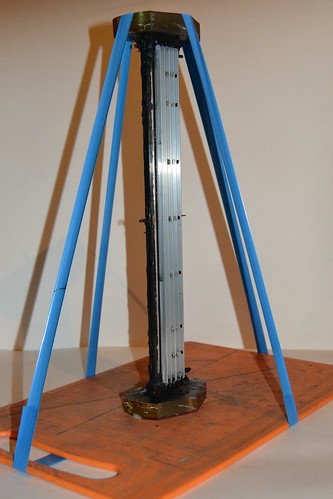
16.02.2017
While the new laser cell is curing (and it can take as long as two weeks)
some more measurements were taken. I measured the tolerance of the laser to
the mirror misalignment and to the type of peaking capacitors being used.
On the misalignment
To simplify the description lets choose a coordinate system. Let the Z-axis
be directed along the optical axis of the laser (along the laser channel. Let
X axis to lie in the plane of the waveguide and be orthogonal to Z-axis. (The
x-axis is essentially collinear to the direction of the electric current or
either to the direction from one electrode to another). And finally let Y axis
to be directed orthogonal to the waveguide plane.
Here is a picture (hopefully it will clarify the things rather than mess them
up even more):
          ^ Y
          |
  ========|==================
          +--------> X
  ===========================
Let's remember that in the process of the alignment we direct the alignment
laser beam throughout the resonator of our CO2-laser and observe the spots,
produced by the beams reflected by the front and rear mirrors. Let's call these
spots as "alignment spots."
In the taken coordinate system it was obtained that moving the alignment spot
(related to the front mirror) by 1 cm along the Y-axis (both upwards and
downwards) drives the laser to the threshold with correspondent reduction of
power by 10 times. Even slightly more movement of the front mirror and the
laser can not reach the threshold.
Along the Y axis the threshold corresponds to the alignment
spot motion of
3 cm.
It means that the required tolerance of the alignment is ±10 mrad in the
plane of the waveguide and ±3 mrad in the direction normal to the plane of
the waveguide. (The distance from the alignment laser to the front mirror was
150 cm and we are noting that the beam deflection is twice of the mirror
deflection.)
The resonator was of the stable type. Having both concave mirrors. The rear
one was spherical with R=2m radius; the front one was hybrid one, and the
radius of its spherical part was also 2 m.
The sensitivity to the alignment in the vertical plane appeared to be
unexpectedly high. It makes me think that I need to expand the waveguide a bit.
For example to 4 mm.
On the tolerance to the capacitors type.
In practice capacitors are described not only by their capacity and endurable
voltage. There are at least ESR and ESL parameters:
- ESR - equivalent series (active) resistance;
- ESL - equivalent series inductance.
The ability of the capacitor to heat, when alternating current flows through
it, is determined by its ESR. And the lowest possible discharge time (or the
short circuit current, as You wish) is determined by ESR and ESL both.
Here is some other thing, that should not be related with the current laser,
but to the full extent determines the behaviour of TEA lasers. It is the
dependence of the dielectric permeability of segnetoelectrics to the applied
electrical field. As the result the accumulated electric charge q quits to
depend linearly to the applied voltage U. In other words the law q = C * U
(where C is the capacity of the capacitor) changes its status from the precise
to roughly approximate. It also means that even all three parameters (C, ESR
and ESL) are not enough for the complete description of the behaviour of the
capacitor. E.G. TEA CO2 lasers work best with ceramic doorknob pulsed
capacitors and tend to fail with (seeming to be) low inductance Maxwell ones.
So the theory as well as practice tells us that different capacitors can
lead to different results even in case they have the same capacity. Needless
to say it is interesting to see how the type of the peaking capacitors can
affect the present laser.
The tests were made using the mixture of CO2:N2:He = 1:2:6. The mixture was
aged seriously. The resonator was: rear mirror concave, the front mirror -
the hybrid one.
The initial test (the reference point) was made with using 3 pcs of ceramic
doorknob pulsed capacitors rated to 2 nF x 40 kV each. They were connected
to the laser cell by wide aluminium stripes.
Results:
| Threshold current (as indicated by the gauge) |
2.5 divisions (42 mA peak) |
| Current of drop to arcing |
4 divisions (68 mA peak) |
| Lasing average power |
25 mV (160 mW) |
The peaking capacitors were then replaced by the ones having plastic mold
body insulation and wire terminals. The capacitors were of the ceramic type,
and rated to 40 kV 2 nF. Their capacity was verified by a multimeter. However
even the first glance at them can tell You that they would definitely fail
under the advertised voltage - the gap between the terminals is less than
15 mm. Many of them come with cracks in the ceramic discs with corresponding
degradation of the performance. Their seller named them as "Muratas" but I
refuse to hope that such a serious manufacturer could throw such a bad thing
into the market.
Three of such capacitors were connected in parallel to the laser cell. The
connection was made by copper wire 1 mm in diameter. Subjectively the laser
began to work a bit worse. But the sensation is not verified by figures:
| Threshold current (as indicated by the gauge) |
between 2.5 and 3 divisions (48 mA peak) |
| Current of drop to arcing |
a bit less than 4 divisions
(68 mA peak) |
| Lasing average power |
20 mV (130 mW) |
The results should be taken as "nothing has changed in the limits of errors."
And finally the peakers were replaced by three K73-13 (mylar film, rolled
type) rated to 2 nF x 10 kV. This time even the figures can prove that it
became worse:
| Threshold current (as indicated by the gauge) |
a bit over 3 divisions
(51 mA peak) |
| Current of drop to arcing |
3.5 divisions (60 mA peak) |
| Lasing average power |
16 mV (100 mW) |
After the laser had been returned to its initial state (after connecting
the doorknob Muratas) it gave 24 mV - i.e. the output has returned too.
19.02.2017
An attempt was made to increase the power of the ionizer by means of finer
match of the AC-oscillator (Feron) to its load. In order to do this, different
numbers of turns in the secondary winding (the one feeding the ignition coil)
were tested. In the range from 10 to 20 turns the difference was barely notable.
The limiting current, the threshold and the laser output were essentially the
same. Finally the winding was returned to its original 15 turns.
Another thing that was done this weekend was a little upgrade to Feron
electronic transformer, used as the ionizing oscillator here. Namely a 1000 uF x 450 V electrolytic capacitor was attached to the output of the internal diode
bridge inside the Feron unit. So now the ionizer works in continuous mode,
not in the pulsed one. Still testing, and now I can say only that the Feron
unit is still alive but the laser seems to have lost some power.
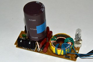
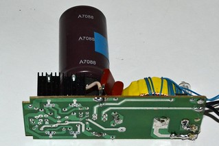
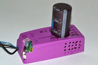
24.02.2017
The cell with copper electrodes is now ready. Frankly speaking it should
stand for another week, but lets call it a day.
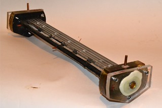
Here's how the laser looks like with the new cell:
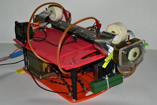
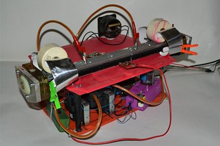
The electrodes are made of copper wire (3mm dia). There were real problems
with its straightening. The most simple way to make it straight is to stretch
it until it breaks. The diameter of the wire after stretching will be slightly
smaller, but this is allowable. Near the very point of the break the diameter
will be considerably smaller, but one can always discard that part.
To pull the 3 mm copper wire until it breaks by hands only is a Herculean
task. And if the piece is long enough (like 10 meters) any jacks and handles
are out of the job too. Finally it was decided to tie the wire to a trailing
hook of one car and pull the wire by another car. It appeared to be unexpectedly
hard to break the wire even by force of car. Fortunately no harm to health and
life was inflicted. I will abstain from describing all the fun here. Lets leave
it for the imagination of Yours.
For the ones, who wants to reproduce the experience, i have only one hint:
You better sand the wire from the oxides before trying to stretch it.
Otherwise You can easily bend so precious straight piece of the wire just by
rubbing it with a sandpaper.
The wire was straightened, and a pair of suitable pieces were cut from it.
After some sharpening and cleaning those pieces became the future electrodes.
They were glued in between two flat glass plates. The sizes of the laser sell
were kept intact: laser channel width 30 mm; waveguide thickness 3 mm; length
of the active part 350 mm; length of the glass walls 400 mm and length mirror-to-mirror 450 mm.

Aside the different material of the electrodes the other difference of the
new cell is that the coolers-ionizers are made not of the hollow rectangular
aluminium tube, but they are made of E-shaped aluminium extrusion. It is
supposed to operate as an air-cooled heat sink. I'm still wanting to avoid
using water as long as possible. Ask why? Remember the written above about the
microwave oven transformer and electric arm-chair.
The new cell was tested on argon containing mixtures: CO2:N2:Ar = 2:3:15 and
CO2:N2:Ar = 1:2:3. It was also tested with some helium containing mixture,
which initially was CO2:N2:He = 2:3:15.
Let me remind, that the cell with the aluminium electrodes almost always
allowed to reach the discharge current of 3 divisions as indicated by
milliammeter, and it was possible to get up to 4 divisions from time to time.
The interesting property is that the top obtainable current depends weakly to
the N2 to CO2 ratio and to the type of the buffer gas being used.
On argon mixtures the cell with copper electrodes appeared to be able to bear
up to 5 divisions of current (as indicated by milliammeter) usually and
up to 6 divisions - occasionally. However the output growth il less
considerable. The threshold has grown up to 4 divisions. It seems like the
main factor of the average current increasement is the increasement of the
pulse duration rather than the increasement of its amplitude. But I've still
not bothered to use the oscilloscope to check it up.
With helium based mixture CO2:N2:He = 2:3:15 the top current, limited by the
arcing, appeared to be the same 3..3.5 divisions as it was with aluminium
electrodes. In this particular case that laser haven't reached threshold. The
helium was (obviously) from a party balloon (newly bought however).
After a proposition that the mixture still lacks helium, it was diluted with
helium twice by volume. I.e. it became something like CO2:N2:He = 2:3:35.
Nevertheless, the current of dropping to arcing was still equal to 3 - 3.5
divisions of milliammeter scale (at pressure of 1.2"Hg). One might note that
with this mixture the laser was able to reach the threshold, but the output
was lamentable.
Carefully (for not to let the air in) into the vessel with the gas mixture a
little droplet of xylene was added. And still the surge current did not change.
But the threshold became unreachable again.
It was supposed that argon may be somehow responsible for higher current on
argon based mixtures. So argon was added to the mixture. The amount of the
addition was ~25% of the total mixture volume. It became then something like
CO2:N2:Ar = 2:3:35:10. And the surge current did again make us happy with its
constantness. There was no lasing too.
Finally, almost by fortune, the mixture was diluted by nitrogen. The amount
of the nitrogen was not measured - a part of the volume that had been expended
in the tests was filled. Kinda like 10 - 20 % of the volume. I.e. it became
CO2:N2:He:Ar = 2:8-13:35:10. (Or if we divide it by two: CO2:N2:He:Ar = 1:4-6:18:5).
After the addition of the nitrogen the mixture has suddenly stopped to behave
bad. The surge current has risen to the values already obtained on the argon
mixtures: 5-6 divisions of milliammeter scale, There appeared lasing. And
not only just appeared... The power has surpassed 240 mW. The mixture with its
almost unknown composition has shown nearly the best result.
Difficult to name the exact value of the optimal CO2 to N2 ratio for this
laser, but it definitely likes plenty of nitrogen.
With the argon based mixture and with this (unknown composition) one a video
was taken, how the laser lights some matches:
With CO2:N2:Ar = 1:2:3 the highest obtained power was 25 mV (160 mW).
With unknown He based mixture the top power was 42 mV (269 mW).
The heat builds up during the laser's operation. The thermal inertia of the
laser cell is just enough for five minutes before the output starts to drop due
the overheat.
28.02.2017
Usage of the copper electrodes has really allowed to increase the limiting
current (achievable before dropping to arcing). But it takes place with "good"
mixtures only and the amount of this increasement didn't even reach 2 times.
With average mixtures the cell with copper electrodes behaves almost like
the one with aluminium ones.
The further point in our checklist is to see whether the discharge
characteristic will become more soft when using the constant current rather
than pulsed one. Let me remind that now the laser is fed by a half-period
rectifier, i.e. by pulses having 50 Hz repetition rate. The ionization
generator has already been prepared for the constant operation (see the record
of 19.02.2017). Lets go further.
Three new diode stacks were soldered up. Each of them contains 8 x HER308
diodes, connected in series. The new stacks plus the old one were assembled
into the full rectifying bridge.
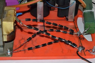
There is still no smoothing capacitor, so
the laser cell is now fed by pulses with 100 Hz repetition rate. (It should
be considered when trying to interpret the values of current indicated by the
milliammeter. Its gear does the time averaging of the acting forces, so
the pulses with the same amplitude but with the doubled repetition rate will
probably lead to doubled indication values. But this is in theory. In practice
it just means that recalibration is needed.)
After the modifications the laser was assembled, aligned and got a run.
With CO2:N2:Ar = 1:2:3 the power has grown to 45 mV (288 mW).
With the helium mixture of the unclear composition (see the record of 24.02)
it reached 70 mV (450 mW).
The power rise with the argon mixture was 1.8 times so far, and with the
helium mixture - 1.7 times. Ideally the output power should be exactly doubled
in both cases. And we got a bit less. But I think that it is too early to
panic, because in range of errors and instabilities it more looks like the
things go right.
Such a power allows not only to burn up a match. But also to burn through
a sheet of paper. Even a white one. It seems that CO2 laser should ignore
the type of paper - the black one as well as the white one should absorb
10.6 mcm well. But in practice the difference is more similar to the one
we observe when using a neodymium laser - the white paper is much harder to
burn. Here's the video:
There's still no water cooling and the overheat of the laser cell comes less
than in 3 minutes. And if one wants to measure something or to have some fun,
he needs to move his... fingers.. quick to have a time to increase the current
gradually (not letting the arcing to develop) and for the rest stuff.
And finally the output of the rectifying bridge was loaded with a smoothing
capacitor. A microwave oven HV capacitor rated to 0.9 mcf was used. Its value
was intentionally taken lower than needed - it should keep the duty cycle below
100% keeping the heating at the reasonable level.
The result is that with smoothing capacitor laser failed to reach threshold
on argon mixture at any pressures. And on the "good" hellium mixture it barely
reached threshold at optimal pressure. Lemme describe this in more details.
After the smoothing capacitor was connected the limiting current (the one when
the laser drops to arcing) became lower by 1..2 divisions of the
milliammeter scale. Moreover, if earlier the approach to arcing was smooth -
the laser behaved more and more unstable while approaching the surge current,
and here the laser suddenly drops to heavy arcing (dangerous for the cell
integrity) without any warning signs. The approach became sharp and dangerous.
And if the arcing took place even for a short time the laser appears to be
completely overheated and needs a half of an hour to cool down.
It seems like the current pulses (when feeding without smoothing) play kinda
arc-quenching role. When the arc tries to develop, just in a couple of
milliseconds the voltage vanishes and the discharge becomes unable to sustain
itself. And it takes place 100 times per second. This allows more safe and more
close approach to arcing, and even (dynamically) to slightly surpass it.
On the other hand when we use a smoothing capacitor nothing can stop the
development of the arc once it happened. The arc does not quench even in the
valleys between pulses, because of the non zero current there.
06.03.2017
(Abt myself:) Did You got what You said?
In the introduction to this web-report i named the kind of the discharge,
which ionizes this laser, as "barrier type". Why not use the old good term: "electrodeless discharge of the capacitive type"? Additionally I used a bit
lousy definition, saying that "the electrodes are insulated from plasma".
Naturally on the contrary to the "true" electrodeless discharge the barrier
one has no need to be electrodeless. The insulation layer is still present
there, though. The schematics below show three types of discharges, where
some dielectric between the electrodes makes an obstacle for the direct
discharge - makes a "barrier" in its way:
     |
     |
//---+---//
///////////


///////////
//---+---//
     |
     |
1) both electrodes are insulated (true electrodeless discharge of the capacitive type) |
     |
     |
//---+---//
///////////


 ----+----
     |
     |
2) one of the electrodes is insulated (barrier type discharge) |
      |
//    |    //
//  --+--  //
//         //
/////////////
//         //
//  --+--  //
//    |    //
      |
3) none of the electrodes is insulated the dielectric blocks the direct way for the discharge |
The barrier may be set at both electrodes (here the discharge becomes "true"
electrodeless), at one of the electrodes, and finally away from the electrodes.
The last two types of the discharge are not electrodeless, but still the
current there is determined by the displacement current, that arises during
the charging process of the distributed capacity of the dielectric surface.
(Certainly the dielectric has to be strong enough. If it was broken down the
discharge becomes the common one, based on the conductivity currents.)
If one looks attentively at the scheme of the laboratory laser (see the
second picture in the introduction to this web-report), one can discover
that there is an electrical connection between one of the ionizing electrodes
and one of the electrodes of the main discharge. The connection goes through
the grounding. I.e. respectively to the external high frequency ionization
the laser is connected not as the electrodeless discharge circuit.
The said is not related to the "LANTAN" laser. It cannot be seen from the
picture in the introduction, so i need to cite another picture from the same
book [1]:

Here one can clearly see that the LANTAN uses namely the electrodeless
scheme. (By the way if we are speaking about a non-sustainable form of the
discharge, it is curious, why the authors of the cited works, do continuously
use the term "preionization"? Looks like a bad habit.)
What's the difference? First of all the type of the connection does affect
the external ionization discharge power.
The high frequency discharge is connected to the external high frequency
(or the pulsed one) oscillator through a capacitor. The first plate of this
capacitor is the cooling - ionizing electrode, the second plate is the plasma
itself, and the dielectric layer is the glass wall of the laser cell. When the
plate has sizes 35 x 5 cm, the glass wall is 2 mm thick and the dielectric
permeability is 5, the capacity of the planar capacitor will be:
Ci = 8.85e-12[F/m]*5*0.03[m]/0.002[m] = 232 pF.
In case of the "true" electrodeless discharge the laser is connected to the
HF or pulsed oscillator as this:
 _/\_  Ci||     +-----+     || Ci
  o------||-----|LASER|-----||------o
         ||     +-----+     ||
And the energy, depositing in plasma with each recharging of the capacities
is: Ei = q * Ui, where q - electric charge, having passed through the plasma,
ui - voltage drop on the plasma.
The electric charge q is equal to the one, that accumulates on the capacitor
plates, when the capacitor charges to the voltage Uc (the voltage that feeds
the circuit). I.e. q = (Ci/2)*Uc. A half of the Ci is taken due to the fact
that here we have two similar capacitors connected in series.
The voltage drop on the plasma can also be estimated easily. The measured
voltage drop over the main discharge was measured and appeared to be 1.7 kV.
And the length of the ionization discharge (3 mm)is ten times less than the
length of the main one (30 mm). So Ui = 170 V. The charging voltage is harder
to estimate, so lets take it from handwaving: Let it be Uc = 10 kV. Then
Ei = (232e-12/2)*1e4*170 = 1.97e-4 J. At the frequency f = 20 kHz the
ionization power will be 8 W (with taking into account that the recharging
takes place twice a period). And those 8 watts are from 250 watt rated
oscillator (Feron electronic transformer).
Actually the question whether our oscillator is capable to develop the said
voltage on the said capacity is unclear. To illustrate this let's estimate
the required power as the energy, needed to charge the capacitor to the given
voltage (Ci*Uc^2/2) multiplied by the frequency of recharges (2f):
Wi = 2*2e4[Hz]*232e-12[F]*(1e4[V])^2/4 = 232 [W]
The estimation shows clearly that it is not easy even for 200 W rated Feron
to recharge the ionizing capacities at 20 kHz oscillation frequency. However
fine load matching allows to approach the mentioned 10 kV.
In order to use the power of the oscillator effectively one should aim to
the equality Us ~ Ui. However the lower voltage allows only lower currents,
and thus lower powers of the ionization. One could increase the current by
increasing the frequency, but it may affect the simplicity of the design
(and many people consider the radio-frequency technique as being hard and
complicated one).
Setting aside the increasement of the voltage and increasement of the
frequency, what's left? Increasement of the Ci capacity. And exactly in this
point the schematics of LANTAN laser circuit and of the laboratory laser
circuit do differ strongly. If we use the same simplification to draw the
ionization circuit of the laboratory laser as we did it for the electrodeless
discharge, we'll end with a strange picture:
                      ||Ci
                   +--||----+
                   |  ||    |
                   |        |
 _/\_  Ci||     +--+--+     |
  o------||-----|LASER|-----+-------o
         ||     +-----+
Despite it is strange, the circuit is distinguished by the fact that the
laser is connected in series with Ci capacity rather than with Ci/2 as it
took place before. And it is twice as much.
One can develop this idea further and draw:
 _/\_  Ci||
  o--+---||---+
     |   ||   |
     |        |  +-----+
     |        +--|LASER|-------------o
     |        |  +-----+
     | Ci||   |
     +---||---+
         ||
And it corresponds to the connection through 2*Ci capacity already - i.e.
four times greater than it was in the initial variant. And this is absolutely
for free. It does not require exotic materials or very thin walls. It even
does not require to build a new laser cell. Just reconnect the old one in the
new way and presto...
One needs to connect both cooling/ionizing electrodes by means of some wire.
(Care must be taken to avoid flashovers from this wire to other parts of the
circuit.) And to connect one terminal of the high frequency/high voltage
oscillator to any of the ionizing electrodes, and to connect the another
terminal of the oscillator to one of the main discharge electrodes.
And finally we get the next circuit:
                                      two ignition coils
                                       in parallel +-------+----------+
            +---------------------------+          |       |          |
   o--------|  +---+         )|         |---o--- |(        |  Laser   |
  ~ 220 V   | /_\ ---  Feron )|( 16     |       )|(      =====        |
            | \^/ ---  250 W )|( turns          )|(   +--)   (--+     |
   o--------|  +---+         )|         |---o--- |(   |  =====  |     |
            +---------------------------+          |  |    |    |     |
                                                   |  |    +----)-----+
                                                   |  |         |
                                                   +--)---------+
  microwave                                    Rb     |         |
  oven              8 x HER308                 3k4    | Cp 4 nf |
  transformer  --+--|>|--...--|>|--+-------+--/\/\/---+---||----+
   4kV      ||(  |                 |       |                    |
   o------- ||(  |                 |       |                    |
           )||(  |  8 x HER308     |       |                    |
           )||(  +--|<|--...--|<|--)---+   |                    |
   o------- ||(                    |   |   |                    |
            ||(                    |   |   |                    |
               |  8 x HER308       |   |   |                    |
               +--|>|--...--|>|----+   |  --- Cf                |
               |                       |  ---                   |
               |  8 x HER308           |   |          /         |
               +--|<|--...--|<|--------+---+-------(ma)---------+
                                                   /
The scheme has marks that the electronic halogen lamp transformer Feron has
suffered the next modifications: the secondary of its internal toroidal
transformer was replaced and a smoothing capacitor was added to its internal
diode bridge rectifier. It is also shown that now the main discharge is fed
by full bridge rectifier rather than by a half-wave one.
The laser was assembled and aligned. The cell with copper electrodes was used.
And there was still no smoothing (Cf=0).
On the CO2:N2:Ar = 1:2:3 mixture it was obtained 50 mV (320 mW)
With a (new fresh) CO2:N2:He = 2:5:21 mixture it was obtained 110 mV (700 mW)
Most of the "powerful blue" (450 nm) laser pointers, that are positioned as 1 Watt rated on the market, do really not more than 600 mW. And after a couple of years of storage they drop to 0.3-0.5 W. So the laser being described here did successfully surpass that powerful laser pointers. And i'd like to hope that it is still far from its limits.
As one can see from the schematics, now the high frequency (HF) power is
applied between the cathode and both (connected one with each other) coolers - ionizers. Other types of the connection were also tested. Among them the one,
when the HF voltage is applied between the anode and both coolers-ionizers. The
one when one of the ignition coils is connected between anode and first cooler- ionizer, and the second ignition coil is connected between cathode and the
second cooler-ionizer. The latter case was tested with the coils connected
in-phase and in opposite phases. Any of tested alternatives was worse than
the variant, shown on the figure above, but still better than the "true"
electrodeless connection.
Just another interesting thing to note is that with "true" electrodeless
connection the discharge was almost uniform, while with the barrier discharge
connection it has stratified into multiple of streamers. Since the pressure is
low the streamers are wide - almost 3 mm wide. The dark gaps between the
streamers are ~ 1 mm wide. It might be bad, but apparently does not affect
lasing.
And finally to the output terminals of the rectifier, that feeds the main
discharge, a smoothing capacity was attached. Initially it was a humble 1 mcF,
which has grown to Cf = 4 mcF later.
With the CO2:N2:Ar = 1:2:3 mixture it gave 90 mV (570 mW)
With the fresh CO2:N2:He = 2:5:21 mixture it did 170 mV (~1100 mW).
The current of surging to arcing (as indicated by the milliammeter) has
reached 70 mA. The lasing threshold was 50 mA.
The top achievable current does not depend to the mixture type in the limits
of +-5 mA. The same can be said about the lasing threshold.
It is interesting that with the old circuit ("true electrodeless") using the
smoothing capacitor caused that any arcing undoubtedly meant the stop of the
laser. 30-50% reduction of the supply voltage by the variac was not sufficient
to suppress arcing. And with the new scheme (barrier discharge) the arcing
can be stopped by 15-20% voltage decreasement. And the approach to the arcing
limit itself has become soft. - The laser warns its user by sudden and short
flashes inside the cell and by waving of the milliammeter arm. In addition
the arc lost its tendency to sit at the single (chosen) spot. It became
possible to enter the mode of "running arc" again.
It feels like the additional alternating voltage of the external ionizer
blows the arc off. It is possibly due to the nulls of the current flow, or
even due to the repolarizing (which probably causes quenching of the cathode
spots).
The power of the laser has finally grown to the 1 watt level. It is still an order of magnitude lower than it was expected, but it already can perform some interesting things.
07.03.2017
Since the capacity of the external ionization circuit has grown by 4 times the
transformer ratio of the ignition coils has become too excessive. As an attempt
to match the load once again the ignition coils were replaced by a television
flyback transformer. Its name is TVS110-PC15, but You are unlikely to find one
outside of Russia. So i'll say that its secondary has 1500 turns and it is
wound on a ferrite with high saturation level. (Power ferrite.) Magnetic
permeability of the ferrite is 3000. Its section is 1.8 square cm. The primary
of the flyback transformer is of low use here. A new winding was added instead.
It has 4 turns of thick (3 sq. mm.) wire in PVC insulation. The winding is made
with 2 wires simultaneously (totally 6 sq. mm.).
The secondary of the internal toroidal transformer inside the Feron unit was
also replaced. Now it has 4 turns of the same (double) wire (totally 6 sq.mm.).
                                     TV flyback
                                       transformer +-------+----------+
            +---------------------------+          |       |          |
   o--------|  +---+         )|         |---o--- |( 1500   |  Laser   |
  ~ 220 V   | /_\ ---  Feron )|( 4      |   4   )|(turns =====        |
            | \^/ ---  250 W )|( turns    turns )|(   +--)   (--+     |
   o--------|  +---+         )|         |---o--- |(   |  =====  |     |
            +---------------------------+          |  |    |    |     |
                                                   |  |    +----)-----+
                                                   |  |         |
                                                   +--)---------+
  microwave                                    Rb     |         |
  oven              8 x HER308                 3k4    | Cp 4 nf |
  transformer  --+--|>|--...--|>|--+-------+--/\/\/---+---||----+
   4kV      ||(  |                 |       |                    |
   o------- ||(  |                 |       |                    |
           )||(  |  8 x HER308     |       |                    |
           )||(  +--|<|--...--|<|--)---+   |                    |
   o------- ||(                    |   |   |                    |
            ||(                    |   |   |                    |
               |  8 x HER308       |   |   |                    |
               +--|>|--...--|>|----+   |  --- Cf = 4uF          |
               |                       |  ---                   |
               |  8 x HER308           |   |          /         |
               +--|<|--...--|<|--------+---+-------(ma)---------+
                                                   /
Spark test of the new oscillator can be disappointing at the first glance.
It gives only 4 mm of spark between two thin wires (read - between sharp
objects). More attentive inspection shows that the wires melt in these tests.
It means rather low voltage but decent power.
With this external ionization generator:
With CO2:N2:Ar - 1:2:3 the laser did 110 mV (700 mW)
With fresh CO2:N2:He = 2:5:21 the laser did 328 mV (2100 mW)
The pressure was 1.2 inches of mercury in both cases. The laser cell had
copper electrodes and the rectifier of the main discharge circuit had smoother
capacitor of 4 mcf (4pcs of microwave oven capacitors in parallel).
By turning the variac's handle gradually one can easily put the arm of the
milliammeter onto its limiter (the average current has surpassed 100 mA
without dropping to arcing). The threshold of lasing is somewhere between 60
and 70 mA.
One can see that the circuit in its present embodiment has reached its limits.
The ballast resistor Rb is needed to be reduced, the milliammeter's shunt
is needed to be reduced (with the following calibration of course), the
smoothing capacity Cf is already too small, and so on.
PROJECT STATUS:
• the power of the laser has surpassed 2 W;
• full efficiency of the laser has surpassed 1%;
• differential efficiency is about ~3%
09.03.2017
The scheme was upgraded. Now its ballast resistor consists of three 6.8k ones
in parallel (resulting to 2.26 kOhm). The milliammeter's shunt is now formed
by two 2 Ohm resistors (resulting to 1 Ohm). Feron halogen lamp transformer
unit was moved into "the chassis of the power supply". The smoothing capacity
was kept unchanged - I had no more capacitors to attach there.
For some reason after the reassemblage the old type of the ionizator connection
(between the cathode of the cell and the pair of its cooling parts) is no longer
optimal. It allows the current to be only 5 divisions of the milliammeter
scale before dropping to arcing. While the connection to between anode and the
pair of the cooling parts allows to reach 7 divisions. By the way it ruins the
idea that the alternating current of ionizer helps to suppress arcing by
dimming the cathode spots. Apparently the reason is not in the polarity, but
rather in the parasitic coupling.
Generally the parasitic coupling plays a great role in high voltage high
frequency circuits. For example even Alfonso Rodriguez has noted in his blog
that the next two circuits give completely different results when used to feed
a TEA nitrogen laser.
        ||
   +----||--+-----------+
   |  Cs||  |           |
   |        |  LASER    |
   V        +--)  (--+  )
SG          |        |  ) Lc
   ^       ---       |  )
   |       ---       |  |
   |        |        |  |
   +--------+--------+--+
   |
  ---
   -
|
    SG
 +--> <----+--------------+
 |         |              |
 |         |  LASER       |
 |Cs       +---)  (---+   )
---        |          |   ) Lc
---       ---         |   )
 |        --- Cp      |   |
 |         |          |   |
 +---------+----------+---+
 |
---
 -
|
And it despite the fact that they are essentially identical from the point of
view of the electricity. The reason here is in the parasitic capacities between
the parts of the circuit and its common (earth) wire. If one takes them into
account the schemes become completely different.
Another example is the well known Marx bank circuit. The circuit looks simple,
and works in reality. But if one attempts to model it in any of the electronic
modeling software (i.e. Microcap et. al.) the computer will be glad to inform
that the circuit refuses to do anything good. And only the careful addition of
the (parasitic) capacities to the ground wire and other parts allows finally to
set it alive.
Our case looks similar. The geometry of the circuit has changed, the parasitic
capacities have changed too, - so the very other variant of the connection has
become optimal.
The maximal registered laser power with the new circuitry was 365 mV
(2300 mW). It was wit CO2:N2:He = 2:5:21 mixture and of course in the gas flow
mode. The pressure, when this maximal power was attained was equal to 1 inch Hg.
It is lower than it was in previous tests.
The power level of 2 Wt allows not only to light a match but also to cut it
into halves (see the short video below):
Naturally, the experience of laser pointers use shows that with some skills
and persistence one can cut a match even with 1 W rated laser. However the
2 W one does it easier, as You could see in the video clip.
At the working laser the oscilloscope traces of current and voltage were
taken.
The voltage (when the current was 6 divisions of milliammeter scale and
the gas pressure was 1 inch Hg):

The voltage (when the current was 6 divisions of milliammeter scale and
the gas pressure was 1.2 inch Hg):

In both cases a voltage divider 1:1000 was used, so one volt on the trace
means one kilovolt applied to the laser cell electrodes. The voltage drop on
the cell became lower. If earlier it was 1.7 kV at 1.4"Hg pressure, that
meant 1.2 kilovolts per inch, then now it is almost equal to 1 kv/inch. The
possible explanation: now the power level is higher, so the gas is hot and
has lower density of its molecules at the same pressure. In its own turn it
means lower electric strength and lower voltage.
One may also conclude that the filtering capacity Cf is enough - there are
no pits in the voltage having the frequency of 100 Hz. Some insignificant
(probably) oscillations are present, but their frequency has nothing to deal
with the mains and the rectifier.
If the things are generally clear with the voltage, one can not say the same
about the current. For example here is the trace of the current (voltage over
the 1 Ohm shunt) at the gas pressure 1 inch of mercury and when the
milliammeter indicates 6.5 divisions:

At the beginning I thought that those are interferences of the glitches of
the oscilloscope software, that connects the sampling points with solid lines
(yes it happens, if You are using a digital oscilloscope). But the frequency
of the oscillations (~400Hz) does not allow to relate them to any of the known
sources of interference. The mains - 50 Hz, the rectifier - 100 Hz, the Feron
electronic unit - several tens of kilohertz, RC oscillations of the Rb+Cp chain
repose even higher. The proposition that these are the glitches does also fail,
because the traces are reproducible from test to test, with may be 10%
variations of frequency and amplitude.
With changing of the applied current the shape and frequency do change too.
Here is the current when the milliammeter shows 6 divisions:

This is probably may be somehow related to the 100 Hz pulsations of the
rectified voltage, however the traces of voltage make this doubtful. But
here is a couple of traced taken at 7 divisions of milliammeter:


Neither the frequency nor the shape does conserve from test to test. Only
the mean current value does. However it is evidently due to the fact that
it is set manually by turning the variac handle and looking onto the
milliammeter indications.
From those traces I can only say that 7 divisions of the milliammeter scale
correspond to nearly 140 ma of the average current through the laser cell and
to about 300 mA of the peak one. 7 divisions in this tests are almost exactly
at the dropping to arcing limit. The lasing threshold is 4.5..5 divisions.
Interlude 2. Radiotechnical
28.03.2017
One can see that the laser is starving for ionization power. If the power
being put into the gas from the external source could be risen, say, 5 times,
the laser would give all that we want from it and maybe with some surplus.
However the external generator in the form of the Feron with some ignition
coil or with a flyback transformer has almost approached to its limits.
Naturally there exists some reserve here: e.g. one could cut the cooling-ionizing
electrodes into segments and apply two Ferons or more. However
this solution is not beautiful. And it will stick when the voltage on the
electrodes will reach 30 kV and the insulation will start to fail.
It would be good if we increased the external ionizer frequency towards
several megahertz, and the cuvette would be included into some tank circuit
in order for not to force the generator to produce hundred of watts of the
reactive power in vain.
The search of some cheap and powerful high frequency transistors has
forced me not to rely upon my own abilities and to make some internet surfing.
After a long doubt whether the results should be shown here or not I finally
decided to do it. It may be interesting for laser hobbyists even if it can not
be applied directly to enhance the laser.
SUDDENLY: MANY OF THE "POWER SUPPLY" TRANSISTORS APPEAR TO BE ABLE TO OPERATE
AT SEVERAL TENs of MEGAHERTZ! And since for the purposes of the external
ionization (btw for the direct pumping too) it is more than enough to reach
only 10 MHz, there is no need to buy the expensive UHF transistors having the
shape of golden screws or plates. One can easily adopt the power supply MOSFETS
that can be easily bought or even scavenged from the olden power supply units.
Looking at the results that the internet people achieve one can decide that
most of the "take-it-first" transistors can operate at 10 MHz and above. Not
only the fast and light-gated irf510 and irf840 can do it, but also the heavy
weighted IRFP460 or pondering IRF3205 can.
2.1. Slayer Exciter
Maybe the first schematics, one faces to, when searching the web for the
HV HF things, is so called "Slayer Exciter". This term has its own author and
operation principle, but the socium has its own ways. The thing being widely
called as the "slayer exciter" has low relation with the original author and
principle. As far as i could get the term "Slayer Exciter" means the whole
class of schematics, that can be determined as:
THE SLAYER EXCITER IS THE RESONANT OSCILLATOR WITH THE CURRENT FEEDBACK BEING
TAKEN FROM THE GROUNDING LOOP OF THE MAIN TANK CIRCUIT.
In the simplest case it can be formed by a single stage circuitry having only
one transistor. More complicated variants can contain multi stage amplifiers
and phase correctors.
A simple slayer exciter circuit is shown below:
                     V
           30 mm dia |
             250mm   )
             long    )  -----------------+
             coil    ) (                 |
             of      ) ( 5 turns         |
             0.18 mm )  --------------+  |
             wire    |                |  |
       R1 1k         |       R2 5.1k  |  |
   +---/\/\/---------+-------/\/\/----+  |
   |                 |                |  |
   |  20V   / 20V    |                |  |
   +---|>|--|<|------+                |  |
   |     /           |                |  |
   |                 |  VT1 IRF840    |  |
   |                 ---              |  |
   |                -------           |  |
   |                |  ^  |           |  |
   |   R3 3 Ohm     |  |  |           |  |
   +---/\/\/---+----+--+  +-----------)--+
   |           |                      |
   |  c1 10n   |                      |
   +----||-----+                      |
   |           |                      |
   |  C2 10u   |                      |
   |    ||     |                      |
   +----||-----+                      |
   |    ||+                           |
   |                                  |
   |           Cf1 2 x 470n           |
   +----------------||----------------+
   |                                  |
   |                || Cf2 10u        |
   +----------------||----------------+
   |                || +              |
   |                                  |
   |                                  | VL1 protective lamp
   |                                 (X)
   |                                  |
   O GND                              O +20 V and more
The automatic biasing circuit R3C1C2 provides the negative feedback for
the direct current and hereby helps to get rid of the classical pots (variable
resistors) in the gate circuit. Moreover when the slayer exciter oscillates the
voltage drop on the R1 resistor (occasionally) allows to make the source to
be more positive than the gate and thus to move the transistor into "C" class
for higher efficiencies and lower heat dissipation.
The salt of the circuitry is that it has intrinsic property to excite the
tank exactly at its resonant frequency. And it does not depend to the coil or
whatever. The scheme does either operate resonant or does not operate at all.
To comprehend this fact lets redraw the feedback signal path in the next way:
                       +-----+
                       |     |
                       )     |
 ...-+--|              )     |
        |              )     |
     +->|L--...----+---      | C "Secondary-to-ground"
     +--|    C     |        ---
     |    "gate to---       ---
     |     source"---        |
     |             |         |
     +------...----+---------+
Here we've drawn the stray capacity from the top of the secondary coil to
the earth in the explicit form. One can note that the feedback circuit now
looks like the classic "resonant capacitive transformer", being widely used
in the output stages of radio transceivers for the impedance matching with
antennas. The capacitive transformer here does transform the low current and
high voltage at the secondary top into the high current low voltage near the
gate of the transistor. Because the gate capacity of some powerful FET is
usually large the high current is really welcome here.
The bipolar transistor slayer exciter principle is generally the same, with
the single difference that the base-emitter junction with the protective diode
attached in the opposite direction do work as the short circuit here rather
than as the capacitor. (Usually Your want to protect Your transistor from being
killed by the overvoltage. In case of MOSFET you will use a pair of
anti-parallel zener diodes connected between the gate and the source. And in
case of bipolar transistor You will use some fast diode, attached between the
base and the emitter in the direction opposite to this junction conductivity.)
So with the bipolar transistor we actually can not use the capacitive
transformer to imagine how it works. And in order to comprehend how the high
voltage and low current is being transformed into the low voltage and high
current needed to control the base we need to refer to the terms of "standing
wave", "node" and "antinode" of current, with taking into account that the "reflection" of the secondary coils "in the earth surface" complements the
quarter-wave circuit to the half-wave one.
The schematics is simple as an anecdote and if You have a droplet of a
(radiotechnical) humour, You will want to make it and check. Even despite the
fact that its practical use is somewhere near zero. The frequency is low, the
efficiency is low, and the loading capacity is low (the oscillations tend
to stop when trying to harvest any reasonable power).
When replicating the scheme it is bad to get rid of the auto-biasing circuit
connected to the source (R3, C1, C2). Without it the MOSFET's begin to behave
like matches. Bipolar ones are more tough, but the magical RC circuit will be
useful even with them. If the device refuses to operate from the first try -
one should interchange connections of the primary coil. The fresh assembled
circuit should have a probability of being made correctly of 50%. Its mystics,
but whenever I've did slayer exciters or blocking generators or similar ones
it always requires to exchange the connection of the feedback coil. Even when
(knowing this fact) I had exchanged the leads beforehand.
Here's a snapshot of a brush discharge produced by a single-transistor slayer
exciter when the feeding voltage was 30 V and the current was 1 Amp.
2.2 The Classique
Three schemes were compared. (The protective zener diodes are not shown for
the sake of clarity and simplicity).
A) Meyssner-Armstrong Oscillator with the external tank circuit. (Resonant
oscillator with an inductive feedback in the form of a separate coil). The idea
was to make the coupling coils L2 and L3 to have small number of turns while
the main tank coil L1 has large number of turns, providing high Q-factor and
high voltages.
   +----------------+------------------+--------o +12..24 V
   |                |                  |
   |      +-------  ) L3               |
   |   C1 |    L1 ) )  ---------+      |
   |     ---      ) ) (         |      |
   |     ---      ) ) ( L2      |      |
   |      |       ) ) (         |      /
   |      +-------  |  -----+   |      \ R2
   |                |       |   |      / 2k2
   |        VT1     |       |   |      \
   |        IRF510  +--|    |   |      /
  ---        ...       |    |   |      |
  --- C5    IRF840  +->|L---+   |      |
   | 100n           +--|        |      |
   |                |           +------+
   |     +-----+----+           |      |
   |     |     |    |       C4  |      |
   |     |     |    /      10n ---     /
   |  C2 |+  C3|10n \ R1       ---     \ R3
   |    ---   ---   / 3.0       |      / 1k
   |    ---   ---   \           |      \
   |     |     |    /           |      /
   |     |     |    |           |      |
   +-----+-----+----+-----------+------+-------o GND
B) The capacitive tri-spot circuit (Clapp-Colpitz oscillator.) The resonant
oscillator with a feedback through the capacitive voltage divider C1a,C1b,
being included into the main tank circuit. Here we can again observe a
pi-network (capacitive transformer) in the main tank circuit. If C1a and C1b
are large and C1c is small then we should be able to achieve high voltages on
the coil.
   +-----------------------+-----------+--------o +12..24 V
   |                       |           |
   |                   +---+---+       |
   |                C1a|       |       |
   |                  ---      |       |
   |                  ---      )       |
   |                   |    L1 )       |
   |      +------------+       )       |
   |      |         C1b|       )       |
   |      |           ---      )       |
   |      |           ---      |       |
   |      |            |       |       /
   |      |         +--+       |       \ R2
   |      |         |  | C1c   |       / 2k2
   |      |         | ---      |       \
   |      |         | ---      |       /
   |      |         |  |       |       |
   |      |         |  +-------+       |
   |      | VT1     |                  |
   |      | IRF510  +--|               |
  ---     |  ...       |               |
  --- C5  | IRF840  +->|L-------+      |
   | 100n |         +--|        |      |
   |      |         |           +------+
   |      +---------+           |      |
   |                |       C4  |      |
   |                /      10n ---     /
   |     +-----+    \ R1       ---     \ R3
   |     |     |    / 3.0       |      / 1k
   |   L2)     |    \           |      \
   |     )     |    /           |      /
   |     )     |    |           |      |
   |     |     +----+           |      |
   |     |                      |      |
   +-----+----------------------+------+-------o GND
C) The inductive tri-spot circuit. (Hartley oscillator - the resonant one with
a feedback having the form of a tap of the main coil).
   +---------------------+----------------------+--------o +12..24 V
   |                     |                      |
   |                     |                      /
   |                     |                      \ R2
   |                     |                      / 2k2
   |            VT1      |                      \
   |            IRF510   +--|                   /
  ---             ...       |                   |
  --- C5        IRFP460  +->|L---+--------------+
   | 100n                +--|    |              |
   |                     |       |              |
   |          +-----+----+       |  C4          |
   |          |     |    | R1   --- 10n         |
   |          |     |    / 3.0  ---             /
   |       C2 |+  C3|10n \       |              \ R3
   |         ---   ---   /    +--+---+          / 1k
   |         ---   ---   \    |      |          \
   |          |     |    /    |      |          /
   |          |     |    |    |C6    )  ---+    |
   |          +-----+----+   ---   L2) ( L1|    |
   |                     |   ---     ) (  ---   |
   |                     |    |      ) (  ---   |
   |                     +----)------+ (   |C1  |
   |                          |      )  ---+    |
   |                          |      )     |    |
   +--------------------------+------+-----+----+--------o GND
Judging by the output power, by the variety of the transistors that agreed
to cooperate, and by the easiness of starting, the undoubtful leader is the
Heartley scheme. This result is more than expected, however. With the HF
bipolar transistors it was the same - if wanting highest power from the
simplest circuit, get ready to make the inductive tri-spot.
The looser is the capacitive tri-spot. The heavy or slow MOSFEt's don't
want to oscillate here at the highest frequencies. The lighter ones (a la
irf510 - irf840) are happy to work here but the power does not impress.
The network suffers from the skew of the main tank circuit, when trying
to increase the oscillations voltage by reducing of C1c and increasing C1a
and C1b.
The Meyssner's one did give intermediate results. Ideally it should not
be worse than the inductive tri-spot, but in practice, when one tries to
optimize the turns numbers and positions of the L1 and L2 coils, the scheme
has a strong tendency to switch the modes. The mode of oscillations having
the L1C1 tank circuit as the frequency determining one is often less stable
than the one that Uses L2 and the source to gate capacity of the transistor
or the one that uses L3 with the drain-to-gate capacity.
Why to want the external tank circuit rather than rely on the internal one?
It looks much simpler to attach some coil in parallel to the laser cell to
form a tank circuit (of the frequency unknown:) and to couple an exciter to it,
that can oscillate at the native frequency of the laser cell + coil system.
The alternative is to make an oscillator with a pre-set frequency, and expend
tons of efforts in order to tune the laser cell + coil to resonance with that
pre-set frequency. And one is lucky enough if having only one tank circuit in
his oscillator.
The Hartley circuit (at least in the form pictured above) has at least three
modes:
- the one having L1C1 tank as the frequency determining circuit,
- the one having L2C6 tank as the frequency determining circuit,
- the one that determines its frequency by means of some part of L2 coil and
the internal capacities of the transistor.
Amazing, but the mode with the external frequency determining tank appears to
be rather stable. Especially when the Q-factor of the external tank is high and
the ratios of frequencies of the external tank and the internal one are close
to some integral number.
The photo and video below show the example of the inductive tri-spot
oscillation "on the external mode". The frequency is 1.6 MHz. The native
frequency without that "Tesla column" was 3.65 Mhz. The power supply params
were: voltage ~50V, current ~1.5 Amps.
The internal microphone of the camera suppresses bass tones and the
impression after watching the video is poor when compared to the one when
looking at this with one's own eyes. Naturally this "brushy" hisses and growls
rather scary. Note the needle pin, cooling from the white hot state after
switching the oscillator off. Also note the splashes of the molten metal
(looking like orange sparks) when it operates.
2.3. ZVS push-pull
           R1             +---+----+
         50..100 Ohm      |   |    |
      +---/\/\/--------+  |   |    ) L1 2x0.5microHenry
+24V  |                |  |   |C1  )
 <----+    R2          |  |  ---   +----+
      |  50..100 Ohm   |  |  ---   )    |
      +---/\/\/---+    |  |   |    )    |
 <-+              |    |  |   |    |    ) L2 >100 microHenry
GND|    +---------)----)--+   +----+    )
  ---   |         |    |           |    )
   -    +---|<|---+    +----|>|----+    )
        |  D1      \  /    D2      |    |  +20..100V
        |  HER506   \/    HER506   |    +---->
        |           /\             |
        |    U1    /  \      U2    |    +---->
 U1,2   +--|      /    \        |--+    | GND
IRF540     |     /      \       |      ---
...     +--||   /        \     ||--+    -
IRFP460 +--|+--+          +----+|--+
        |      |          |        |
        |      \ R3   R4  \        |
        |      / 10k  10k /        |
        |      \          \        |
        |      |          |        |
        +------+----------+--------+
               | GND
              ---
               _
The schematics is interesting by the fact that it is not a pure self-sustaining
oscillator. A 24V external direct current source serves as the gate
driver here. It charges the gates through R1 R2 resistors and then they
discharge through D1 D2 diodes and very low drain-to source resistance of the
open transistor of the opposite shoulder.
While the diodes stay alive and the auxiliary power source does not fail
the voltage at the gates won't exceed the preset one (24V) and hence one can
omit the protection zener diodes.
The main part of the circuit (drain network) can be fed by a sufficiently
higher voltage and current. Do note, however, that the L1C1 tank circuit tends
to oscillate with a high amplitude and the total voltage at the sources can
exceed the feeding one by 2..3 times. Therefore if one uses, say, a transistor
with 400V source-to drain allowed voltage, then the circuit should not be fed
by a voltage higher than 130V. If one uses lower voltage rated FET's, like
irf 540 or irf3205 the limitation to the power supply becomes like 30 V.
The output is suitable to be made by means of an inductive coupling. One can
wind a coupling coil (1..2 turns) above the main coil and connect loading there.
By using high voltage transistors (irf840, irfp460), by precise choice of the
load and by adding a small ballast resistor (of about 10 Ohms) one can attain
the operation of this circuit directly from 220v mains (with some rectifier).
It allows not to use a powerful transformer or PSU.
The circuit is proof to the loosing of oscillations. One can note that if
we exchange the inductive load by a resistive one the circuit will turn out
to be a well known trigger. And this one can have only two stable states. In
any of them one of the transistors is fully open while another is fully shut.
In any case the power dissipation is about zero. So there would be no overheat
in case of oscillation fail. Apparently with no oscillations there will be no
overvoltage. The sole thing that can suffer from this situation is the power
supply unit (in most cases it load ability is lower than the top current those
mosfert's are rated to).
The L1C1 tank circuit makes the trigger astable and turns it into an
oscillator. The circuit can operate at any frequency of the L1C1 tank network
provided that the gates are charged in time through the R1 R2 resistors. In my
tests a small 24V power supply (actually another FERON with a rectifier) was
used to drive the gates. In those conditions IRFP460 succeeded to do 480 kHz
and IRF540 did 1 MHz.
A curious fact: the circuit is fully operational when fed by auxiliary power
supply only. I.e. with the main power unit being disconnected. In this mode
the circuit oscillates (at the natural frequency of L1C1) and produces
noticeable power - several watts of output. However it is too small for this
circuitry. And when one connects the main power supply the output rises
drastically.
The circuit can also operate when fed without L2 choke. The choke does simply
limit the consuming power.
The most interesting property of the circuit is indeed the low heat of the
transistors. At any tested levels of power they stood cool. The switching mode
allows them transfer tens of volts and amperes without notable heat. It makes
an impression that one can easily get it to very high power at reasonably high
frequency.
However the impression is fallacious. The fact that the transistors stay
cool does not mean that everything else is cool too. The resistors R1 R2 for
example are hot enough to boil a cup of tea. But this is still not the main
problem. A kettle is finally a kind of resistor too. The most unwanted thing
is that D1 D2 diodes are hot to crackle and smoke. And the overheated diodes
tend to increase the reverse current. And it causes leakage of the high voltage
from the oscillating powerful tank circuit to the tender gates of the
transistors. The most pitiful thing is that the diodes appear to stay alive after all (after cooling down) and the transistors are not.
Among the things in access the best results were with HER type diode (HER506
etc.). Even when their plastic was scorched and their legs were cindered they
continued to work. On the contrary the (seeming to be) powerful 10A10's caused
the death of many MOSFET's. As the mockery they have survived themselves.
Shotckey diodes from computer PSU's (like 20FQ040) have low reverse voltage and
still play hot dogs.
As the result ZVS push-pull has shown itself like beast-powerful but low
frequency device. And the limitation to the frequency is set mostly by the
diodes. Transistors with light-weighted gates (2nf IRF510) can operate up
to 1 MHz. The heavy weighted ones (4nF, IRFP460) did it only up to 0.5 MHz.
But it is only for a short time. The prolonged operation is possible only
at the frequencies 2-3 times lower.
2.4. The common push-pull oscillator
           || C4 47nf
    +------||---+
    |      ||   |        Q1 IRF510, IRF540N, IRFML8244, etc.
    |           |
    +----/\/\/--+---+ +  +-----------------------------+------+
    |   R1 3 Ohm    | V  |       C2 1 nf               |      |
    |              --------         ||                 |      |
    |                --         +---||----+            | L1   |
    |   R3 1k        |          |   ||    |            |      |
    +----/\/\/-------+          |         |       2 trn )     |
    |                \          |         |             )     |
    |                 \       --+--/\/\/--+-------------+     |
    |                  \     /                    2 trn )     | C1
    |                   \   /    R6 3k3                 )    ---
    |                    \ /                       +----+    ---
    |                     \      R4 3k3            | 2  )     |
    |                    / \                       |trn )     |
    |                   /   \---+--/\/\/--+--------)----+     |
    |   R5 1k          /        |         |        | 2  )     |
    |                 /         |   ||    |        |trn )     |
    +----/\/\/-------+          +---||----+        |   |      |
    |                |              ||             |   |      |
    |                --          C3 1 nf           |   |      |
    |              --------                        |   |      |
    |   R2 3 Ohm    | ^  |  Q2 IRF510, IRF540N...  |   |      |
    +----/\/\/--+---+ +  +-------------------------)---+------+
    |           |                                  |
    |      ||   |                                  |
    +------||---+                                  |
    |      || C5 47nF                              |
    |                     ||  C6 47nf              |
    +---------------------||-----------------------+
    |                     ||                       |
    o                                              o
   GND                                           +12..24V
The circuitry resembles the ZVS one shown above. But the diodes are changed
to capacitors C2 C3. And the gates are "hanged between the ground and the sky"
by means of biasing resistors R3/R4 and R5/R6. As usual the LC tank circuit
tends to swing to double or triple of the feeding voltage. So the feedback
capacitors C2 C3 are better to be attached not to the drains of the opposite
shoulder transistors, but rather to some tap of the L1 coil. As the bonus You
will get lesser influence of the gate capacity onto the resonant frequency.
As the result the L1 appears to consist of four sections. (In my case each
section contained two turns of 1 mm copper wire. It means 8 turns total.
And all this thing is wound over a rod, having the diameter of 11 mm. Over
a glue gun rod to be more precise. After winding the glue gun rod was
extracted from the bore of the coil. With C1 capacitor rated to ~1nf and
irf510 transistors this oscillated between 11..13 MHz. I've heard that a
technological radio band is placed there. By reducing C1 and L1 the frequency
could be pulled to about 22 MHz. Further on the circuit goes to a blocking-oscillator mode and the resonant frequency of L1C1 has low effect on the
resulting frequency. The natural frequency of this HF blocking oscillator
appears to be at 7.5 MHz with irf510.
On the contrary to the ZVS circuitry, here the transistors do heat. If one
sets the biasing on the gates to be lowest possible, still providing the self
start of the oscillations, one can have the efficiency of 60..70%. Nevertheless
with the subtle irf510-s the RF output of the oscillator was enough for the full
incandescence of some 12V 20W bulb. Transistors' temperature was acceptable.
THE RESULT: the circuit can operate at the frequencies needed. But 20W are
kinda not enough for a good external laser ionizing source. It seems good to
make the similar scheme but with irf540N or irfp460A, however I've got none of
them available with the necessary letter. And the simple ones (540 and 460
without proper letter) aren't capable to operate above 3..3.5 MHz. It takes too
much time to wait for them from the Internet and the local stores again have
no transistors with the proper letter. Moreover in the local stores the price
for a piece is like the one for ten pieces if buying from Ali. ...And also
in addition to the transistors one should get the protective zener diodes
(1.5KE12...1.5KE350 suppressors).
The said above makes one to think that this approach is not affordable enough
for a DIYer. Mabbe those ones, who say that the RF technique is too complicated,
were right... I will certainly continue to build a good RF source and
occasionally will put here the results, but I can not recommend to follow this
way for those ones who have not enough experience with high frequency power
electronics. And for those ones who have this experience, maybe it would be
simpler to take their transmitter, to attach a 200 W antenna power amplifier,
to set a simple impedance matching transformer between the laser cell and
the amplifier and finally to press the talk-listen button to send the power
into the laser.
<continued 04.11.2017>
The parts from the  take long time to arrive. And it is hard to order
exactly the needed ones from the first try. One needs to foresee everything in
advance. Or else it appears that while the parts for 20 wt rated scheme are
still on their way the laser already asks for 40 wt. And while the parts for
40 Wt scheme are coming it appears that 100 Wt needed. take long time to arrive. And it is hard to order
exactly the needed ones from the first try. One needs to foresee everything in
advance. Or else it appears that while the parts for 20 wt rated scheme are
still on their way the laser already asks for 40 wt. And while the parts for
40 Wt scheme are coming it appears that 100 Wt needed.
This way it turns out that the power electronics is a slow work. Nevertheless
from march till november a way from watts to kilowatts was found. Generally if
one had said me at the very beginning that it would take a kilowatt rated RF
power source to ionize this laser, I would send all this branch of the research
into the erotic style journey with the special wish for it to stay there forever.
But what's done is done, and at the end of this (a bit longer than wanted)
radiotechnical interlude I'm presenting the
220V POWERED ZVS PUSH-PULL INVERTOR RATED TO MEGAHERTZ AND KILOWATT
In principle the same scheme was already presented above, but that time I had
no proper parts and lack of the experience, so the output and the reliability
were far from the needed ones. Further an understanding had came that for the
stable operation when powered from the mains, one really needs kilovolt rated
transistors. Yes, fine ballasting and loading can help to reduce oscillations
and to keep alive even irfp460-s. But the laser cell (with and without the
discharge) is far from the ideal type of the load. It tends to suddenly change
its impedance more than by one order of magnitude. And using some parallel
resistive loading or some snubber-type schemes give intolerable heat and even
more requirements for the output power.
Generally as the understanding has come that the circuit has to be working
at the free run, immediately there came the success.
                R1              +---+----+------------------------+
                 25 Ohm         |   |    | C1 = 3n3 KVI-3 x 10 kV |
            +---/\/\/--------+  |   |    ) L1 10 microHenry       |
+15V        |                |  |   |C1  )                        |
 <----------+    R2          |  |  ---   )   +------+             |
            |    25 Ohm      |  |  ---   )   |      |             |
            +---/\/\/---+    |  |   |    )   |      |             |
 <-+                    |    |  |   |    |   |      ) L2 > 100uH  )
GND|          +---------)----)--+   +----+---+      ) 100uH < L3  )
  ---         |         |    |           |          )             )
   -          |         |    |           |          )             )
              |         |    |   ||C4    |          |             |
              +---------)----)---||------+          |             |
              |         |    |   ||      |          |             |
              |         |    |           |          +-------------+
              |         |    |           |          |
              +-|<|-|<|-+    +-|>|--|>|--+          |
              |  D1, D2  \  /   D3, D4   |          |  +310V
              |  STTH806  \/    STTH806  |          +---->
        +-----+           /\             +----+
        |     |    U1    /  \      U2    |    |     +---->
 U1,2   |     +--|      /    \        |--+ C3---    | GND
IXFK   ---C2     |     /      \       |      ---   ---
24N100 ---    +--||   /        \     ||--+    |     -
        |     +--|+--+          +----+|--+    |
        |     |      |          |        |    |
        |     |      V D5     D6V        |    |
        +-----+      -          -        +----+
              |      ^          ^        |
D5, D6:       |      |          |        |  C2=C3=800pf, Teflon diy
1.5KE18CA     +------+----------+--------+
                     | GND                  C4=2200 pF Teflon diy
                    ---
                     -
You can see that the circuit is simple enough for the first glance. One only
has to keep in mind that for its building the printed board is just not enough.
It takes to use a drill, a hacksaw, a filer, screwdriver and wrench...
The transistors are any MOSFETS rated to not less than 1 kilovolt of drain
voltage and for the currents not less than 20 Amps. One should also pay
attention to the channel resistivity in the open state. It should be less than
1 Ohm and generally the lower the better.
In the reality there are not so many types of the suitable transistors
especially having the suitable price. Practically any of them are products of
the Ixys corp. The transistors are mounted onto some heatsinks from the old
Pentium processors. The coolers are installed but weren't used yet.
The diodes
have 15 ns recovery time and I was able to find only 600V rated ones. And those
are tandem type i.e. they contain two diodes in series inside one unit. In
order for them to hold the free running voltage of 1 kV I connected two in
series, meaning the real stack of 4 physical diodes in each shoulder. The
resistors of the gates feeding circuit are four white ceramic rectangular
bricks having 100 Ohms x 5 wt for each gate. Such an assembly heats in
reasonable limits and has suitable inductance. The gates are connected with
sources by TVS protective diodes, rated to 18 v. This helps to keep the gates
alive in conditions of high voltage leaks and interferences.
That's all the commercially available parts. Other parts are diy homemade.
A pair of words on the capacitors. In principle the C1, C2, C3 and C4 capacitors
together do form the sole tank circuit capacity. However its a bad idea to
unite them into the one. At those currents the scheme operates with, the
tremendous affect is given by the stray inductance (of the current path
from the transistor's crystal to the nearest capacitor). Have it 40..60 nH and
You will drown in the gate ringing with the corresponding heating and so on.
On the other hand its hard to find the proper low ESL high voltage capacitor
rated to several kilovolt-amperes and having the suitable size to mount it
directly between the drains with the lowest possible inductance. Therefore
the tank circuit capacity was divided into three parts. The first "snubber"
part - C2 and C3 capacitors - has to be attached directly between drains of
the transistors and the common wire (which should certainly be wide and thick).
The second "constant" part - C4 capacitor - is to be mounted directly between
drains of the transistors. And only the third "tuning" part - C1 capacitor -
can be placed more freely.
C2, C3, C4 capacitors should be mounted DIRECTLY TO THE LEGS OF THE
TRANSISTORS using the WIDEST POSSIBLE metal shims, soldered with a wide seam.
These capacitors must have the lowest possible stray inductance and the
working voltage not less than 1 kV. I could find no commercial product of
reasonable price that could suit. Neither mica nor ceramic ones. So I had
to roll the capacitors by hands. Using the aluminium foil and teflon ribbon.
If You are interested in how to do this You may refer to the pocket sized
dye laser guide where the "candy" type capacitors are described. However
one should avoid mylar here, since it has noticeable dielectric losses at
~1 MHz, which lead to heating melting and breakdown. On the contrary using
the teflon allows the capacitors to stay only warm (i.e. not "hot") at the
nominal power. The free rims near the border of dielectric should be not less
than 10 mm. Yes here is "only one kilovolt" but also "the whole million of
Hertz ", so here are the good conditions for any kind of sliding or brush
discharges.
L2 and L3 chokes are to endure 5 Amps of current and have more than 100
microHenries of inductance. Luckily one may avoid ferrite cores here. Wind
somewhere about 100..200 turns onto some suitable ceramic or glass tubing.
Both chokes can be easily placed on the single tube (2 sections 100 mm long
if the wire has 0.3 mm diameter and the tube has 25 mm diameter). In practice
the chokes stay almost cool. However, just in case, don't wind them on a
plastic tubing.
And finally here is the description of the main coil. The coil is the most
complicated element of the circuit and the most hard to be done. "The state
of the diy art and the miracle of the garage-kitchen technology." This is
due to the fact that You can not choose too large diameter
- it will lead to
the increasement of the length of the wire and the losses will grow intensively
(worth to mention, that the radiation losses increase with the diameter too and
it means the interference that bother others and even problems with the law).
The second reason is that it would be hard to obtain high mutual inductance
when You are trying to collect the power by some secondary coil, when their
diameter is large and the length is short, On the other hand You can not choose
the diameter to be small. First of all due to the breakdowns, and second -
because the coil would melt from heat.
The main problem is certainly the heat. In the inductor ovens they solve it
simply by making the coil of some copper tubing and by letting water to flow
through this tubing. For the obvious reason it is better to avoid any
dependence to the tap water, so it means very very thick wire, coreless coil
with its turns being "transparent" to the natural air flow.
The coil is wound with aluminium wire having 16 square millimeters of section.
There are two layers of winding, The first layer contains 9 turns and can be
wound on some plastic 2 inch sewer's tube. The outer layer contains 9 turns too
and can be wound on some glass or bottle having 65 mm diameter. (Keep in mind
that direction of turns is to be the same in both layers.) Than the parts of
the coil are to be removed from their frames and to be assembled into the
single double layered coil. The electric connection is made by bolting together
the leads of the parts by means of M2 bolts and nuts. To ensure the layers do
not touch each other insert mica insets between the layers.
This is how the complete coil does look like.
In the process of the development many samples of coils were burned out.
(No transistor was lost (!) by the way.) And even such a monstrous coil stays
hot over 100 celsius degrees during the free run of the scheme.
Powering
The circuit requires two power supplies. One of them is made as
rectifier of the mains line voltage and the other on is some independent
unit rated to 12..15 volts and 2..4 amps.
Here is the scheme of the mains rectifier:
          ----  Fuse 5-7Amp
      +--|----|-+
      |   ----  |
 <----+         /
 ~220V 50 Hz    \ thermistor
 Wall plug      /   7 Amp
                |
 <----+         +
      |        / \  Diode Bridge: KBU1009 or 4 x 10A10
      |       /   \
      |   +--+ |>| +------+------------------> to +310 v powering wire
      |   |   \   /       | +
      |   |    \ /       ---
      |   |     +        === 1000 uF x 450 V
      |   |     |         |
      |   +-----)---------+------------------> to GND of the generator
      |         |
      |         |
      +---------+
The rectifier consists of diode bridge rated to more than 10 Amps and more
than to 500 Volts (one may solder it using four suitable diodes, e.g. 10A10)
and of ripple filtering capacitor. The latter should be 500..1000 microfarads
x 450 volts. Good advice: don't choose electrolytic capacitor rated to 300..350
volts here. The rectifier operates in rather heavy conditions and such a
capacitor may just overheat and blow.
Thermistor is needed for the capacitor charging current not to blow Your fuse
plugs and not to kill the diode bridge. IT IS A MUST TO USE A FUSE IN YOUR
POWER LINE! The thermistor can be obtained from some old ATX computer power
supply unit. Here's how it looks like:
In principle the fuse + thermistor combo may be replaced by a sole halogen
lamp, rated to 220 V and 1000..1500 W. However the power output would be lower
this case.
The gates' power supply can be made of some halogen lamp electronic
transformer unit. Use some 40..60 W one. The electronic transformer is used
here without any upgrades or modifications. Just load its output to a diode
bridge and ripple filtering capacitor rated to 500..1000 microfarads x 50 volts.
 <-------------| Halogen lamp      |------------+  4 x HER308
  ~220V 50 Hz  | electronic        |           / \                 to +15v wire
  wall plug    | transformer       |          /   \            of the generator
 <-------------| 12v x 60 W output |---+  +--+ |>| +---+---------------------->
                -------------------    |  |   \   /    |
                                       |  |    \ /     | +
                                       +--)-----+     ---
                                          |           ===
                                          |            | 1000 uF x 50V
                                          |            |
                                          +------------+---------------------->
                                                        to GND of the generator
The bridge diodes better be fast enough. Choose HER or FR series. Yes, they
seem brakish when compared with STTH, but still fast enough when compared to
KBU's or 10A10.
Tuning up the circuit is easy if You have an oscilloscope and, say, variac, or
another 50..100 V power source. Initially attach the oscilloscope in parallel
to one of the protective surge diodes connecting gate and source of one of
the transistors. Then switch the gate-feeding power supply on. The gate voltage
trace should have the shape of "shark fin" - a quarter of sinewave being
distorted slightly by Miller effect.
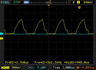
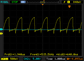
Connect then the main (but lowered) power voltage. The Frequency and
amplitude of the gate voltage oscillations will increase, but generally the
shape of the trace should stay smooth. If there appears some "bloody knead",
You should better not connect the circuit to the full voltage of the mains
(310V).
Having ensured than the voltage on the gates has normal shape, attach the
probe to one of the drains. Use a resistive divider here (1:100 is good) or
else You will end up with dead oscilloscope. The correct drain voltage has
the bell-like shape (well spaced halves of sinewave).
If there are glitches in the form of stray high frequency oscillations
or inductance interrupt peaks, the circuit is also not ready to operate
at full power.
What can one do with the incorrect shape of pulses? The main way is to
revise the geometry of the circuit. Lessen the stray inductances. Any those
snubbers or resistive ballasts are out of help here - the power is too high.
If You have no oscilloscope - well, just design the scheme to intrinsically
have the lowest possible stray inductances. To wire the circuit use shims of
the lowest possible length and the widest possible width. Solder the parts with
wide seam, don't use pinpoint soldering.
When You turn the circuit on for the first time, use only the gates' feeding
power supply. Put an incandescent lamp probe into the main coil. Such a probe
is just a low power incandescent lamp (like 3 V x 0.12 Amps) soldered to a pair
or three loops of a copper wire. Kinda like that:
    +----------+
    |          |
   (           |
   (   +--(X)--+
   (   | Incandescent lamp ~3V ~0.12 Amp
    |  |
    +--+
The lamp should glow when only the gates feeding power supply is switched on.
If it does not, - look for an error in the circuit. If it does, try to add
the drains supply power carefully. Keep an eye to the heating of the
transistors. If they begin to get hot the scheme probably requires rebuilding.
Just for information, my sample of this device showed the temperature of the
heat sinks just below 30oC just after heating the movable part of the tabletop
vise to red hot state. And it is still without turning on the fans.
ATTENTION! THE SCHEME HAS NO DECOUPLED POWER SUPPLY. IT IS FORBIDDEN TO TOUCH
ANY PART OF THE CIRCUIT WHILE IT STAYS PLUGGED INTO THE MAINS!
One may touch
the heats sinks only after (all) the plug(s) have been taken out from the
receptacles. It seems dangerous, but when we use the circuit to feed even more
dangerous device (like high voltage laser) it should not bother too much. Just
keep in mind that the device is not only "untouchable", but in most cases one
should treat it as "unapproachable".
The device can be used as an induction heater. However to reach higher
temperatures its coil should be revised towards more compact design and more
dense field. It may require water cooling though.
One may used it as a powerful high voltage power supply. In order to get
out the power just put a secondary coil over the main one. The circuit can
incandescent a halogen lamp rated to 220vx1000W. Here is the sequence of shots, taken while the device heats a kilowatt lamp. Do note that room lights weren't darkened. The images get darker and darker due to the fact that camera reduces its exposition in trying to compensate the enormous brightness of the kilowatt lamp. I.e. the darkness of the last photos can give You indirect sense how bright the lamp was.
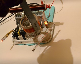


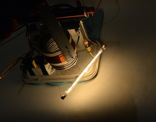
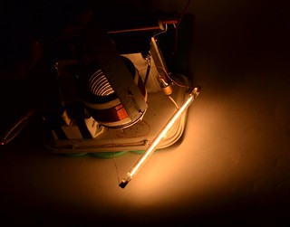
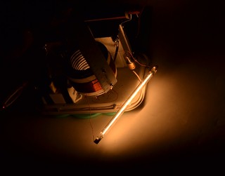
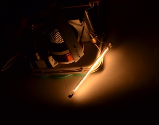
Keep in mind, however, that the lamp of such a power behaves just like a
shortcircuit when cold. In order for not to break oscillations one will need
to limit the coupling between primary and secondary at first, and then
gradually increase the coupling.
When using the circuit as a kind of high voltage power supply one may want
to make a "spark test" of the secondary coil. I should warn You that such
a test is very dangerous. In a second inches of wire turn to vapours and
their place takes a hot arc spaying dozens of droplets of molten copper.
I won't place a photo of this because I have no wish to reproduce this again.
And do note: after such an explosion not only the transistors stay alive,
even the fuse stays not blown off. It means that this fireworks takes place
at nominal level of output power.
<end of interlude>
TESTS OF THE LASER CONTINUES
04.11.2017
Hereby the new generator of external ionization is present. But the laser
lives not so happily. The last of the laser cells (the one with sectioned
copper electrodes 4 mm thick) has dried up shrunk and began to leak. Now
I'm trying to cure the leaks with silicone. And while the silicone is drying,
another cell was scavenged from old stock - the one with aluminium T-profiled
electrodes.
For the try with this cell The external ionization was connected using "electrodeless" schematics (not the "barrier" one). The RF voltage is taken
from the megahertz kilowatt ZVS push-pull unit by a secondary coil having
90 turns of 0.5 mm enameled copper wire, wound on a frame 85 mm in diameter
(a core from some sticky tape bobbin).
The mixture was CO2:N2:He = 2:5:14.
As the result it was got that even only the RF power was able to heat the
laser cell up to the temperature painful to touch (~60oC) in less than two
minutes. If it is due to the heat deposition in the plasma (not in aluminium
electrodes or either in silicone seals) it means that the laser should be
able to operate when being powered by RF only.
The laser was aligned and tested. No lasing was observed when fed by RF only.
When the constant current from microwave oven transformer with its rectifier
was connected to the laser cell it was easy to reach the limits of the
milliammeter scale (~200ma) without falling to arcing.
The shunt of the milliammeter was replaced by one half of an Ohm (was one
Ohm). After this its calibration in statics gives scale division value equal
to 46 mA/div. The ballast resistor was also reconfigured. Now it consists of
two resistors (1 kOhm and 1.3 kOhm) in parallel. It yields 565 Ohm.
Using the mixture CO2:N2:He = 2:5:14 at the pressure of 1.1 inch of mercury
under the current of 6 divisions (~276 mA average if trusting the static
calibration) the laser gave 550 mV by the homemade Peltier calorimeter
indications. Taking its calibration factor as 6.4 mW/mV we can estimate the
output power as 3.5 W.
Here we should note that the calorimeter is not intended for use with so
high powers and one should not treat this value as precise. However due to
the fact that most of the factors of possible non-linearity tend to decrease
indications, this value is most probably a kind of lower estimation.
20.11.2017
In addition to the written above there was one more modification of the
circuit, not mentioned in my previous record. The smoothing capacitor of the
rectifier (the one, rectifying MOT output) was increased to 50 mcf. Those
four microwave oven caps, earlier used, are just not enough for the current
currents.
The described above tests showed that the current of dropping to arcing was
6 divisions of milliammeter and the laser threshold current was 4 divisions.
Curious situation: the current was nearly 10 times higher than the one in
early experiments but there was no success in trying to go far away from the
threshold. To comprehend what's going on a diy kilovoltmeter was installed
in parallel to the laser cell. It was found out that the voltage across the
cell barely reaches 800 volts even at 2 inches of mercury of pressure. I.e.
RF discharge from the kilowatt rated ZVS generator ionizes the gas to such an
extent, that its resistance becomes low and the voltage drop becomes too low
too.
What can be done with that? To try to feed the main discharge with RF current
too? OK, a second sample of the kilowatt rated ZVS generator was built. Quite
similar to the first one.
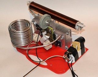
It was attached as follows:
                       +----------------+
                       |                |
                       |              =====
                       |         +--|-     -|---+
                +--+   |         |    =====     |
    ---------   |  |  (          |      |       |
  | KW & MHz |--+   ) (     +----)------+       |
  | rated    |      ) (     |    |              |
  | ZVS #1   |--+   )  |    |    |              |
    ---------   |  |   +----+    |              |
                +--+             |              |
                                 |              |
          -------------          |              |
         | KW & MHZ    |---------+              |
         | rated       |                        |
         | ZVS #2      |------------------------+
          -------------
Its clear that the shunt capacitors across the cell were removed (because
they'd short the RF currents). And also there was no ammeter or voltmeter,
since they're not able to measure the RF values.
A fresh mixture of CO2:N2:He = 2:3:15 was prepared for the tests. And a tiny
droplet of xylene was added to the gas vessel. It was obtained:
feeding type RF/RF;
mixture type 2:3:15 + xylene droplet |
| Pressure |
gauge readings |
| 0.8"Hg |
150 mV |
| 1.5"Hg |
220 mV |
| 2.0"Hg |
180 mV |
| 3.0"Hg |
no lasing at all |
Simply saying two ZVS'es did not allow to surpass the result obtained with
feeding by direct current. For the comparison here are results, obtained with
direct current using the following circuit:
                                 +-----||-------+
                                 |      Cp=12nF |
              +----------+  +----)------+       |
              |          |  |    |      |       |
       -------+-------   )  (    |    =====     |
      | KW x MHZ unit |  )  (    +--|-     -|---+
       -------+-------   )  (    |    =====     |
              |          |  |    |      |       |
              +----------+  +----)------+       |
                                 |              |
                                 |       /      |
                       <---------+-----(kv)-----+
                   1..3 kV from        /        |/
               Microwave Oven Transformer     (mA)
                  with Rectifier               /|
                       <---------/\/\/----------+
                                  Rb=565 Ohm
All other conditions were the same (the same position of the alignment, the
same laser cell, the same speed of the gas flow):
feeding type RF/DC;
mixture type 2:3:15 + xylene droplet |
| Pressure |
gauge readings |
| 1.5"Hg |
480 mV (3.1W) |
| 1.6"Hg |
460 mV |
| 2.0"Hg |
360 mV |
| 1.5"Hg |
180 mV - too slow gas flow |
Here the top achieved laser cell current was 6-6.5 divisions (276-300 mA).
The voltage drop across the cell was not seriously measured (too fast tests,
due to the lack of water cooling), bit it had the order of 800 volts.
At the same conditions but with 2:5:15 mixture having also 0.1ml of xylene
it did 300 mv at 1.0"Hg of pressure. And it was almost the optimum.
The most important problem of the RF ionization is difficulties in the
attempts to hit the resonance with the tank circuit formed by the self capacity
of the laser cell and the inductance of the secondary coil of the oscillator.
When there is initially no plasma in the cell, and it ignites only due to
the applied ionizing voltage (so the capacity is proportional to the charge
of the capacitor), one can show (by calculations in modeling programs) that
this circuit has no resonance for harmonic oscillations. And if the plasma
glows continuously, the capacity depends to the area of surface covered with
this plasma, and to the parameters of this plasma. When one approaches the
resonance, this area increases and the resonant frequency changes. And I'm
not sure that a phase lock circuit could help here. Moreover the complexity
of the phase lock loop contradicts the "KISS" principle.
Exactly due to the difficulties with resonance match it was needed to build
a kilowatt rated RF oscillator, when it needs only 20-50 W of the absorbed
power to reach the ionization needed.
Another way of getting the RF voltage for the external ionization is to
connect some inductance to the laser cell, to kick this tank circuit by some
high voltage pulse and to allow it to oscillate freely. Exactly this approach
was taken by the authors of the works cited in the beginning of this web-report.
I can not say this way is more effective. Its just another. When the authors
write that the energy deposition of the auxiliary discharge was from 20 to 50 W,
so the initiating energy was not more than 10% - it still does not mean that
the energy consumption of the auxiliary discharge generator was also low.
Indeed, let's take the capacity of the laser cell to be 600 pF. And as it is
said in [2] the amplitude of the ionizing pulses was 10 kV. It means that each
pulse the cell was charged up to 10 kv and accumulated CU^2/2 = 30 mJ of energy.
If we multiply this energy by the repetition rate we'll get
30 mJ x 30 kHz = 900 W.
Yet again when reading scientific articles the things look admirable, but
they become not, when one tries to reproduce. However in our case this is
ignorable, because no one gave promise that the efficiency would be high. And
it is interesting what results can give the usage of the "RF interference
generator." (Yes, the pulses of high power and fast decaying oscillations are
the classic form of the interferences. I warned You - keep an eye on the
integrity of Your TV sets and cell phones while working with this thing.)
The schematics of the decaying RF pulses generator is as follows:
                                        C3-C6 mica 0.05 uF x 500 V
                  R1 300 Ohm x 300W   ||       ||
   o------+--|>|----+----/\/\/----+---||---+---||---+
          |         |             |   ||   |   ||   |
 ~220V    |        --- C1         |        |        | Transform ratio
  50Hz    |        === 220uF      |   ||   |   ||   | 1:10
          |         |  450V       +---||---+---||---+     +---------> _/\_
   o------)---------+             |   ||       ||   |     |       Output pulses
          |         |  C2         |                 |  W (        up to 2 kV.
          |        --- 220uF      +--|<|-------+     ) W (
          |        === 450V      /  HER608     |     ) W (
          |         |          ||              |     ) W (
          +--|<|----+      +---+|              |    |  W (
                    |      |     \ IGBT 20N120 |    |     |
                    |      |      |            |    |     |
                    +------)------+------------+----+-----+
                           |
                           |
            _    -> >------+
          _| |_ Rectangular control pulses:
                30us-off  10us-on
                9-12V amplitude
It is rather simple. A wide spread and kinda cheap FGA25N120AN transistor is
used as IGBT here. I won't draw the control circuit - it is trivial and can be
made easily using some 555 timer, some NOT gate and some IGBT/MOSFET driver
(like TC4420). The control circuit yields rectangle pulses with the amplitude
of 9-12 V (dependently to the feeding voltage of the control circuit). The
duration of mark is about 10 mcs and the duration of space is about 30 mcs,
giving together the frequency of ~25 kHz.
The transformer is wound on two U-shaped halves of a TV-set flyback
transformer core. Both halves are set IN PARALLEL, i.e. form a LARGE U-shaped
core, not a small O-shaped one. The wire is rather thick (~0.5 mm in diameter).
The primary has 5 turns and the secondary has 50 turns.
Energy storing capacitors are of mica transmitting type. These ones have low
RF losses. The ballast resistor is 3 water heaters (rated to 500 W each)
connected in series.
When the transistor turns on, the output of the transformer carries a pulse
of fast decaying RF oscillations, having their frequency ~200 kHz. During the
full period the amplitude of oscillations falls by about three times. It is
somewhat faster than desired bit sic.
The laser cell was connected using the next schematic:
                                       Cp 12 nF
                                 +---||---------------+
                                 |                    |
             +----------+   +----)------+----------+  |
             |          |   |    |      |          |  |
     --------+--------   ) (     |    =====        |  |
    |RF Pulse Generator| ) (     +--|-     -|---+--)--+
     --------+--------   ) (     |    =====     |  |
             |          |   |    |      |       |  |
             +----------+   +----+      +-------)--+
                                 |              |
                                 |       /      |
                       <---------+-----(kv)-----+
                   1..3 kV from        /        |/
               Microwave Oven Transformer     (mA)
                  with Rectifier               /|
                       <---------/\/\/----------+
                                 Rb=565 Ohm
It did:
feeding type RF pulse/DC;
mixture type 2:3:15 + xylene tiny droplet;
Laser cell with Al T-shaped electrodes |
| Pressure |
Calorimeter readings |
| 1.2"Hg |
230 mV |
| 1.5"Hg |
330 mV |
| 1.8"Hg |
510 mV (3.2 W) |
| 2.0"Hg |
460 mV |
At the pressure of 1.8 inch of mercury the lasing threshold was 160 mA,
the top achievable current was 300 mA, and it was limited not by arcing,
but by power supply possibilities. The voltage drop across the laser cell
was about 800 V.
I.e. usage of the decaying RF pulses generator allows to obtain almost
the same laser power, as it takes place when using the continuous RF
generator, rated to kilowatt. But the generator of decaying pulses is
simpler and cheaper. Concerning the power consumption, both schemes
eat from the mains the powers of the same order of magnitude.
27.11.2017
From the old stock a laser cell with copper electrodes was extracted.
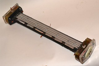 
The possibility of water cooling is completely omitted in the design of the
cell, but still there was no water cooling with the aluminium cell too - due to
leakages of the cooling vessels. So both cells give equal possibilities, with
the exclusion of larger heat capacity of the aluminum one. On the other hand
the previous tests had shown that the copper cell generally gives greater power.
So it is possibly worth trying.
The cell was installed, aligns and connected using the next electric scheme:
                                       Cp 27 nF
                                 +---||---------------+
                                 |                    |
             +----------+   +----)------+----------+  |
             |          |   |    |      |          |  |
     --------+--------   ) (     |    =====        |  |
    |RF Pulse Generator| ) (     +--|-     -|---+--)--+
     --------+--------   ) (     |    =====     |  |
             |          |   |    |      |       |  |
             +----------+   +----+      +-------)--+
                                 |              |
                                 |       /      |
                       <---------+-----(kv)-----+
                   1..3 kV from        /        |/
               Microwave Oven Transformer     (mA)
                  with Rectifier               /|
                       <---------/\/\/----------+
                                 Rb=565 Ohm
There were attempts to run it using the mixture of the next contents:
CO2:N2:He = 2:3:15. Either with xylene or without it, but the laser refused
to give the power. When peaker capacitor was of 12 nF one could achieve
the current of 6 divisions of milliammeter and the output was about 200 mW.
Then the peaker's capacity was decreased to 6 nf. After this the falling to
arcing began to take place at the current of 3.5 divisions. The laser was
just under the threshold. Then the peaker capacitor's capacity was increased
up to 27 nF. But the current of falling to arcing did not rise significantly
(when compared to the initial variant) - 6.5 divisions. The power was 500 mW.
And then exactly in this web-report I found a record that this cell has
already refused to work with 2:3:15 mixture at least once.
The mixture was diluted by nitrogen till the composition became ~2:7:15.
And - YES - with this mixture the problems of the discharge stability just
vanished. The cell yielded 2 watts and after some correction of the alignment
it did 3 watts. In addition it was noticed that with this mixture there was
no optimum for pressure. Ether no normal discharge (immediate fall to arcing)
or three watts already.
In an attempt to increase the heat conductivity of the gas the mixture was
diluted by helium. Till its content became CO2:N2:He ~ 2:7:25. Neither the
power output nor the limiting current had changed. It was still three watts
and 280 mA. No apparent optimum of pressure had appeared either.
Finally a new mixture of CO2:N2:He = 2:5:21 was mixed. (Initially one takes
two volume parts of carbon dioxide and mixes them with five volume parts of
nitrogen. Further one one takes one volume part of this mixture and adds
three parts of helium. And finally one should add a small droplet of xylene
per one automotive tyre of the gas.) The things became better. Here are the
results:
feeding type Pulse/DC;
mixture type 2:5:21;
the cell with copper electrodes 3mm thick |
| Pressure |
Peltier readings |
Current |
| 1.8"Hg |
614 mV |
6.5 div |
| 1.6"Hg |
660 mV |
7.0 div (with some arcing) |
| 1.6"Hg |
740 mV |
7.0 div (without any arcing) |
| 1.2"Hg |
620 mV |
7.5 div |
| 1.8"Hg |
780 mV |
7.2 div |
| 2.0"Hg |
320 mV |
7.0 div |
To illustrate what this laser is able to, a small video was made:
And here are some additional photos:
 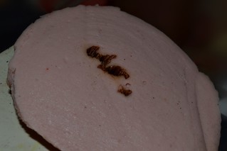
I think that the sausage has brilliantly shown that one should not put his
fingers into the beam. And concerning the useful applications... In principle
there are a lot of CNC engraving and cutting machines having 5 W rated laser
diodes in there. They are able to cut thin leafs of organic substances and
engrave metal surfaces. However this is rather long process and this laser
is still not able for the long runs. It is because it has no water cooling yet.
Well, if not trying to achieve higher powers, one could apply even some air
fans as the coolers here.
Need to say that in the process of testing the rear mirror of the resonator
was broken. It cracked due to the heating by light. It is too far from the main
discharge to receive enough heat from plasma.
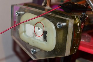 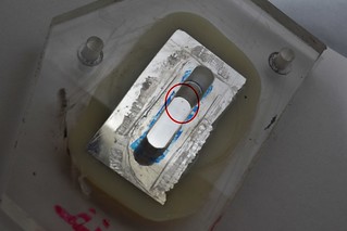
In principle such a behaviour of the mirrors was more than expected from the
very beginning. And there were some thoughts how to avoid this. It is more
amazing, how long it took for the laser to grow up to approach this phenomenon.
Finally its power has reached 5 watts, i.e. about a half of the expected one
from the very start of the project. One can certainly try to increase current
and energy deposition further (by applying good cooling and good ionizer), but...
...But its time to unclose one more reserve of power: we need to increase the
efficiency of the laser cavity (resonator). The deal is that the diameter of
the semi-transparent ZnSe mirror is only 10 mm, while the width of the laser
channel is as large as 30 mm. It means that the most simple scheme (design A
on the figure below) can utilize not more than 30% of light.
The simplest solution would be the design B (again on the figure below) if
I had a 30 mm ZnSe mirror with transparency of 5%...10%. However those mirrors
are expensive, and moreover - they are too rare.

As a simple but compromise solution now I use the design C (see the picture
above). The semi-transparent mirror is installed in a hole inside some larger
and non-transparent mirror. In comparison with the design A it gives a 50%..100%
surplus of the output with all the other conditions are the same. And
nevertheless, due to the problems of alignment of the semi-transparent mirror
with its enframing one; due to the losses on the borders of the enframing
mirror; and due to comparatively large distance between the waveguide ends and
the mirrors I believe that this design of resonator does still utilize not more
than 50% of the useful light power. I.e. just by upgrading the resonator one
can turn this 5W laser into a 10W one.
Great hopes are placed on the design D (see the figure above). It uses
comparatively small mirrors and still the light sweeps all the active volume.
However the design has its own problems. First of all one will have to learn
how to install the mirrors directly into the laser cell. It is needed to
avoid the end losses between the mirrors and the waveguide. And, say... four
little alignment plates for a single laser, is it normal? Secondly: it is
still unclear how to align such a laser, and whether it could be aligned
at all.
PROJECT STATUS:
• The power has reached full 5 watts. It means, the laser can be compared with most elite and expensive laser pointers.
• There is a reserve how to increase the output without any increase of the consumed power: just by redesign of the resonator.
• And there is still some reserve of stability, allowing to further increase the energy load. However a good cooling and more powerful external ionizer will be needed here.
04.12.2017
SUDDENLY: the laser appeared to be able to operate with heliumless mixture.
After the tests described above, the remains of CO2:N2 = 2:5 mixture (used
on the first stage of mixing the helium containing one) were let into the
laser cell. Here are the results:
feeding type Pulse/DC;
mixture type 2:5:0;
the cell with copper electrodes 3mm thick. |
| Pressure |
Peltier readings |
Current |
| 1.2"Hg |
360 mV |
7.5 div |
| 1.35"Hg |
510 mV |
7.0 div with gradual rise up to 9 div |
| 1.5"Hg |
360 mV |
8.0 div |
It means that now the generator of external ionization is powerful enough even
to let the current pass through heliumless gas mixtures. 3.2 Watts of output
look a bit humble when compared to 5 Watts, but no helium means more affordable.
12 Watt reached
09.01.2018
↑
Happy New Year to all of You.
Two new laser cells were assembled. The first one has copper electrodes, the
other one - aluminum ones. Both cells have electrodes ~3 mm thick. The main
feature of the new cells is that the glass walls of their laser channels protrude
through the endpieces and mirror mounts almost to the mirrors of the resonator.
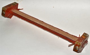
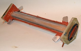
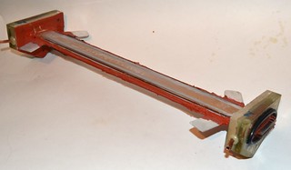

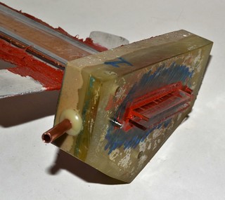
Another feature is that the electrodes of external ionization have planar
shape. This allows to mount large external heatsinks. (It was found
unreasonable to dispose the heatsink together with each broken laser cell.)
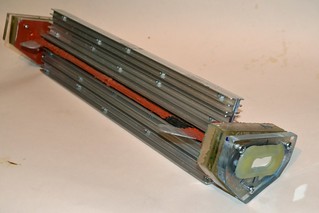
The main sizes are the same for all the cells, beginning from the first ones
described in this report and ending with these being described now. Namely:
the width of the laser channel is 30 mm, the thickness of the waveguide (the
spacing between the glass walls) is about 3 mm, the active length (the length
of the zone occupied by the plasma) is 350 mm and the full length of the
resonator (mirror-to-mirror) is 450 mm.
At first the cells were tested with resonator scheme C (see the picture above)
with the same ZnSe mirror (92% reflectance) having 10 mm diameter and being
placed in the center of the enframing aluminum concave mirror. The external
ionization power supply was the pulse generator based on IGBT transistor (it
was also fully described above).
The main results of the tests are the next:
- The cell with copper electrodes had refused to bear current above 270 mA with
CO2:N2:He = 2:5:14 gas mixture. In order to reach 350 mA and above it was
needed to enrich the mixture with nitrogen. So the new mixture became
CO2:N2:He = 2:7:18.
- With 2:7:18 mixture the cell with copper electrodes appeared to be
operational at pressures up to 2.1"Hg. The optimal pressure was 1.7"Hg. At
this pressure and at 350 mA of pumping current the laser output was ~6W.
- The cell with aluminum electrodes with 2:7:18 mixture was able to operate
at pressures up to 5.5"Hg. The optimal one was 4.5"Hg. At this pressure and
at 350 mA of current this cell was able to give ~6W too. In an attempt to
increase power further the output mirror was killed:
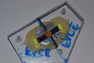
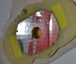
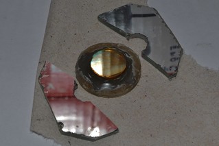
One can clearly see the molten crater in the glass. The size and shape of the
crater implies that inside the cell there was much higher light power than
those 6 watts detected outside.
Moreover the glass walls of the cell had crackled too:
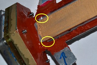
And there is a probability that this crackle is not due the electric heat, but
due to the heating by the laser beam. The crackle was sealed by silicone RTV
and left aside for curing.
The output mirror was replaced by a germanium one having the reflectance of
70%. The germanium mirror has full diameter of 25 mm, but its reflecting part
covers only a disc 15 mm in diameter. The enframing concave aluminum mirror
was not used this time.
With the new mirror the cell with copper electrodes reached ~7W. The top and
optimal pressures stayed unchanged: 2.5"Hg and 1.7"Hg correspondently. The
result looks like good but...
The silicone, used to repair the cell with aluminum electrodes, had finally
dried up, and the cell was tested with the new mirror. The result surpassed
all expectations: the calorimeter readings were 1910 mV. 12.2 W! It was at
the pressure of 4.5"Hg (114 torr or 0.15 bar) and with 350..380 mA of current.
The voltage drop across the cell was ~900 V. The gas mixture was still 2:7:18.
It is interesting that in these tests a shortcircuit bridge between upper and
lower ionizing electrodes was forgotten. I.e. the cell run essentially with
only one ionizing electrode being connected. So the circuit was the next:
                                       Cp 27 nF
                                 +---||---------------+
                                 |                    |
             +----------+   +----)------+             |
             |          |   |    |      |             |
     --------+--------   ) (     |    =====           |
    |RF Pulse Generator| ) (     +--|-     -|---+-----+
     --------+--------   ) (     |    =====     |
             |          |   |    |      |       |
             +----------+   +----+              |
                                 |              |
                                 |       /      |
                       <---------+-----(kv)-----+
                   1..3 kV from        /        |/
               Microwave Oven Transformer     (mA)
                  with Rectifier               /|
                       <---------/\/\/----------+
                                 Rb=565 Ohm
The attempt to recover the error - to connect the second electrode -
lead only to that the top current, achievable without arcing, became 270 mA
and the laser barely reached the threshold.
Apparently with this kind of connection the circuit formed by the inductivity
of the secondary winding of the transformer and the capacity of the electrode
had its resonant frequency more close to the one of the circuit formed by the
primary winding inductance and the storage capacitor of the pulse generator.
Need to say that the previous step-up transformer has unscrupulously burned
out. the insulation between the windings has molten with the consequent
breakdown and breakover. The transistor has survived however. The present
step-up transformer is wound on the same ferrite core (double core from a TV
flyback transformer of medium size). The primary has 6 turns of thick copper
wire and the secondary has 55 turns of enameled copper wire having 0.5 mm
diameter. The primary is wound above the secondary. The insulation between
layers and windings is now made of sticky kapton ribbon (so called "heat
resistant duct tape").
PROJECT STATUS:
• The laser output has reached 12 watts; This is a bit more than it was expected at the very beginning of the project. And this is the level of small commercial laser tubes.
• The necessary vacuum is in range of operationability of affordable DIY vacuum pumps like reversed fridge or automotive compressors
• There probably still exists a reserve to increase the output even further
Considering the comparison to laser pointers. I admit that there is a video on Y_o_u_t_u_b_e that demonstrates a power of a laser pointer based on 7 blue
laser diodes rated to 7w each. Totally 49 watts. It is not so easy to surpass
this result for DIY laser even if it is a CO2 one. Another thing is that those
laser diodes are essentially ready-made lasers and there is a little hope that
one can produce them at home in the predictable future. And they also can not
be treated as affordable and cheap parts easy to obtain by anyone. The things
are not better with the powerful laser pointers themselves. The ones with
output over 10 W are exclusive goods, they cost damned high and they are
piece-work produced. (The scums are out of consideration. Only their labels
cry out about their damned high power. The truth is that most of them give
less than one watt.)
The power of the laser can be illustrated by the next short video:
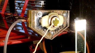
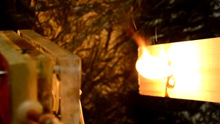
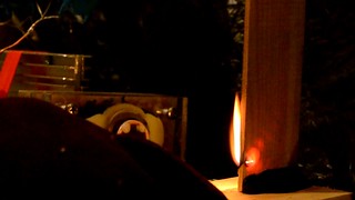
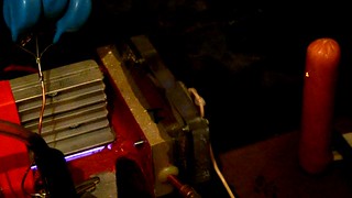
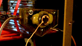
By its unfocused beam it can:
- Charr and burn wood. The output beam spot has rectangular shape, 18 mm
wide and 3 mm high. So the power density is 22 W/square centimeter.
By its focused beam (lens with FL=85 mm) it can:
- Can puncture a finger. Almost throughout in less than a minute.
- In two seconds (after applying full current) it can puncture a 4 mm thick
wooden board.
- It can do a poker-work with as high speed as You can draw.
- With proper mechanics and with proper mode it should be able to cut thin
(up to 6 mm thick) wooden board. When done by hands it gives bad results,
as You could see in the video. It is hard to keep a smooth and even motion of focal spot. And when You miss, the wood becomes embraced with flames
making it even harder, since it obscures the view.
Amazing, but the laser COULD NOT:
- Drill a razor blade. And moreover, the reflected beam was so strong, that
it was able to damage the plastic mirror mount of the laser. So it was
decided to stop the headless experiment.
- Drill through an 1.5 mm textolite from a printed circuit board. (Without the
copper foil of course.) The textolite charrs, swells, hisses and stinks.
But no via hole appears. So this laser still can not be used for PCB
drilling.
- Drill a microscope slider. There shines a little sun on the glass. The glass
melts, flows down, crackles. But there's no via hole again.
It is interesting to note here that the previous experience shows that it takes
only 350 mW of average power (50 mJ at 7 Hz) and 4 minutes of time for a TEA
laser to drill through the similar microscope slider. The hole is large enough
to thrust a 0.1 mm copper wire through it. It means that for the TEA laser
0.35*4*60 = 84 Joules were enough to drill the glass, and the CW laser was
unable to do the same expending as large as 720 Joules (=12 W x 60 sec). Need
to note that TEA laser in that experiment was fed by a "slow" gas mixture
having the N2 to CO2 molar ratio above 3. It allowed to produce rather long
pulses and to some extent avoid the unwanted energy dissipation in the plasma.
(On the contrary if You aim is to obtain the laser spark, You should aim to
as high power as possible and use a "fast" mixture with N2 to CO2 molar ratio
of unity and below.)
The failure to drill the razor blade has shown two points:
| First: |
KEEP YOUR EYES PROTECTED! The reflecting properties of materials for
the deep infrared radiation of CO2 laser differ strongly from ones
for visible light. And You can SUDDENLY get powerful and well shaped
reflected beam from the surfaces not expected to produce it. |
| Second: |
The generic error in the design of the very first laser cell (from the
ones described here) was discovered. Its electrodes had only narrow
chamfers. Moreover they were polished. When the pumping power is high
and the output mirror is too transparent it leads to development of
parasitic lasing in the parasitic cavity formed by the reflecting
surfaces of the electrodes and by the glass walls of the cell. This
parasitic lasing depletes the energy without any use. In case of high
reflectance of the output mirror one can succeed in obtaining lasing
in external cavity, but the losses are too high
In the new laser cell with aluminum electrodes this error is recovered.
The working surface of the electrodes is rounded (by filer) and sanded.
There are no planar surfaces and no polishing. Naturally this explains
the better results: the absence of parasitic lasing and reduction of
light losses on the way between the laser channel and mirrors gives
the opportunity to use 70% mirror, more close to the optimal one. |
The laser was tested with heliumless mixture, but the results were not so
impressive. After some optimisation of gas mixture, pressure and current it
was able to yield 620 mv by Peltier calorimeter indications (3.9W). It looks
humble on the background of 12 W with helium.
The optimal heliumless mixture appeared to be CO2:N2 = 2:5 with the addition
of a small droplet of xylene and a droplet of water per full automotive tyre
of gas mixture (6..8 liters). Without the water there was only 520 mv (3.3W).
The optimal pressure was 2..2.5"Hg.
Additionally on the way to assimilate the schemes with internal mirrors the
laser was tested with a homemade mirror. This mirror was made by hand polishing
of some aluminum plate. The mirror being tested was installed in place of back
mirror of the resonator. The output coupler remained as 30% transmitting Ge
mirror.
In this configuration and with helium based mixture the laser gave 112 mv
(0.7 W).
A guess was made that the handmade polishing had not allowed to keep a needed
shape (of course I failed to make the perfect plane) and the irregular shape
hinders laser power. The mirror was replaced by a commercial one. This time
it was first surface aluminum on glass mirror from some industrial optical
device.
A new test run had shown 22 mv (140 mW).
Both runs were made using CO2:N2:He = 2:7:18 gas mixture at the pressure of
4 inches of mercury.
It is probably incorrect to say that the laser can not operate with plano-plano
resonator. I'd say that plano-plano requires more precise alignment and in
these tests there was no success in achieving the necessary grade of the
alignment. But anyways do note this fact and try not to use plano-plano
configuration if trying to reproduce this laser.
COLANDER
12.02.2018
↑
Wide output couplers for CO2 lasers are not only expensive, they are also
rare. I failed to find one, having transmission 30% and the width of the
working area 25 mm, at any reasonable (for DIY-er) cost.
It was decided to try to make a homemade output coupler. Because the DIY
conditions generally do not allow to make a vacuum dielectric coating with
good properties, it was decided to use a mirror with a number of holes. The
transparency of such a mirror is approximately equal to the total area of
all holes divided by the total (working) area of the mirror.
Obviously one should take one of those household or automotive mirrors
(aluminum coated glass) because their operationability in CO2-lasers was
many times proven. One could drill there a couple of holes, but... The
diamond bores of the necessary diameter had suddenly appeared to be
unaffordable too.
It was finally decided to make a handwork polishing of some aluminum plate
and drill there the needed holes by a common drill and bit.
Grinding and polishing are responsible processes and can not be reduced much.
For example one can not use here a drill with a felt disc and fine abradant.
Or else he will end up with a ruined shape. (We need the mirror to be as
perfectly planar as possible and with the felt disc we will have random hills
and pits there.) One can not shorten a grinding stage - or every
non-uniformities will show up in polishing.
One can, for example, reduce number of polishing stages. I.e. use 3-mcm
abradant directly after 10 mcm one. But in this case it will be needed to
prolong each stage, or the traces of the previous abradant work will be seen
as scratches.
The detailed description of the DIY polishing of optics one can find at
the astronomy hobbyists sites. I will only give a few hints:
The mirror when being grinded and polished should emit a weak and even
hissing sound. If no sound at all - it means the work in vain - You are
not removing metal. The sudden crunch sound means You may stop the work,
wash the mirror, and start from the very beginning - from the most rough
abradant.
Do not underestimate the importance of the chamfers on the edges of the
blank. In the process of polishing the edges can become very sharp. And
not only they can tear the polishing pad, they can also chip, and their
pieces will ruin the polished surface.
Water, when being used as a lubricant, can make the work faster, but it
has a nasty property to dry out. When it dries out the abradant particles
glue up into one large conglomerate and it ends up with that fatal crunch
sound. It often happens suddenly - You see that the polishing pad is still
evenly wet, but several seconds later it appears to be dry with the all
consequences. So if You are not intended to design a dewdrop, You probably should better use a mineral oil.
The material (metal) of the blanks is also of the great importance. Often
the "hatred crunch sound" appears not due to the outer dust, but due to the
fact that another particle of the "intrinsic sand" was opened and detached
from the metal.
The process of grinding and polishing is rather short, when taken alone.
About a half of an hour per each abradant grit (and there are about ten of
them), about a half of an hour for washing and cleaning between the stages.
Totally it takes about ten hours of work to get a really good mirror...
However the sudden tearings of the surface and shape disturbances will force
You to repeat the work again and again. So my final advance here:
If You have even a minimal possibility to avoid the polishing of a homemade
laser mirror - AVOID IT AT ANY COST!
...The first three polished plates were just shameful to look at. It was
senseless to try them in the laser. Well, its my fault - I tried to "deceive
the nature" - to reduce efforts and time needed for the process by some
tricks. The conclusion is: if You want a good result, don't try any tricks, -
just honestly, patiently and accurately perform every stage.
The fourth sample looks like that:
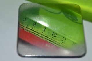
One can see that the reflection of the ruler is straight enough, what means
the mirror is more or less planar. It can be barely seen on the photo, but
the mirror surface is covered by a net of tiny tiny scratches. This is the
result of the work of my finest abradant. I have no abradant finer grit than
1.5 mcm and this one leaves "hair-thin scratches", seen in the visible light.
But it should be OK for the laser, since its working wavelength is 15 times
longer than the one of the visible light, and the surface of the mirror should
behave as ideal for the infrared.
Then the holes were drilled. Diameter of the most large IR windows I have
is equal to 25 mm. It means that the working area of the mirror is 3x25 mm
(remember: 3 mm is the height of the laser channel/waveguide). 30% of
transparency corresponds to 22.5 sq.mm. of the total area of all the holes.
In its own turn it corresponds to 12 holes, each having 1.5 mm diameter. Before
drilling the mirror was painted with protective varnish, and during the
drilling it was pressed between two wooden planks. And despite all protective
measures, a narrow mat area appeared around the holes. The width of the mat
hem was about a quarter of millimeter. I.e. from the point of view of the
light losses in the resonator, one may treat the holes as being 2 mm rather
than 1,5 mm wide. So the reflectivity of the mirror appeared to be 50%
instead of the expected 70%.
Its a pity but the holes can not be drilled before grinding and polishing.
Otherwise one will end up with a wide deep pit around each hole.
Despite the shortcomings, the mirror was installed onto the mirror mount
and sealed with using a kalium chloride window above all the holes:
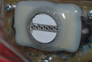
Test run of the laser on CO2:N2:He = 2:7:18 gas mixture has even shown a bit
of output: about 120 mW. At the highest current and at the pressure of 3"Hg
the laser was barely above the threshold.
The mirror was removed and polished to repair the mat areas around the holes.
The mat has gone, but deep and well polished pits appeared instead.
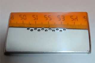
With this mirror the laser completely refused to lase.
Further on the mirror was shifted to the position, where the laser channel "sees" only one row of holes. This is a simple way to reduce the transparency
of the mirror from 30% to 15%.
With this position of the mirror the laser agreed to lase, and, after
some tuning of the alignment and pressure it gave about two watts (309 mV
by Peltier calorimeter).
It was checked out that the replacement of this mirror by a germanium one
with the reflection of 70% allows to get more than 10 Watts easily.
The obtained result causes ambiguous feelings. It is good that hand working
allows to make a mirror, with which the laser not only barely works, but also
gives a decent output. On the other hand the quality of the homemade mirror
appears to be low enough to kill all the expectations to improve the output
in comparison with the commercial grade mirror. Even with the one being not
well suited for the task.
29.01.2019
As You could expect (see the interlude on vacuum tight sealing) up
to the moment all the cuvettes (built in the previous year) have lost
their vacuum tightness.
This was proved experimentally (indeed there was a bit of hope, that
it might be not true) an then the cuvettes were dismantled. Usually one
can reuse the mirror mounts and (in happy case) the electrodes. The glass
walls and heat sink plates are surely to be discarded.
Before the dismantling the cuvettes leaked with the rate from one to
four inches of mercury column per hour. An inch per hour is somewhere
near the limit of acceptability for the use with gas flow mode. And
four inches per hour is too much of leak even for the gas flow mode.
In order to search for a solution how to make the cuvettes more
long living, an attempt was made to build a new cuvette, being sealed
with epoxy resin. Its physical parameters were just the same as for
the previous cuvettes:
the active length (the length occupied by the discharge plasma) - 35 cm;
full size (mirror-to-mirror) - 44 cm;
inter electrode spacing - 30 mm;
thickness of the electrodes (and the plasma column too) - 3 mm;
walls material - common glass, 2mm thick;
electrodes material - aluminum;
The main differences from the previous cuvettes are:
- that the sealing was made not by silicone caulk, but by epoxy resin;
- that the mirror mounts were 3D-printed.
As for the 3D printed mirror mounts - they appeared to be completely
discouraging. They leak heavily even if their fill ratio was set to
100% during 3D-printing. I had to remove them (happily the glass walls
succeeded to survive) and replace by epoxy molds, just like ones, used
in previous cuvettes.
With those mirror mounts the cuvette demonstrated good tightness:
the leak rate was less than an inch of mercury per 24 hours.
Using a gas mixture of CO2:N2:He = 2:10:18 I made several test runs of
the new cuvette. Until the pressure was not yet choosen and the runs
were short (not more than 15 sec at full current load) the things looked
good. But when the proper pressure was finally found and a run was made
aimed for the top power measurements (about a minute at full current load)
the cuvette cracked and lost its tightness. I had barely enough time to
measure the output. The calorimeter readings were 10 Watts.
I'm sorry, but I have no photos of the cuvette to present here. Initially
it was thought, that the cuvette would be photographed in the process of
operation. And later there was nothing to photograph.
In principle the result was expectable enough. In the process of operation
the cuvette is to bear much of heat. And the differences in heat expansion
factors of glass aluminum and epoxy resin cause too much of the mechanical
stress for the cuvette to bear. Still it was a guess, and now it is the fact.
Now one can say for sure, that any cuvette of such a type must be glued
only with some kind of elastic glue.
29.02.2019
One could use a hot glue as a kind of elastic glue. Let me remind here, that "hot glue" means rods of low molecular polyethylene, used in a hot glue gun.
In principle the cuvette was successfully assembled and sealed. It was even
installed and turned on. However the heating of its electrodes was so strong,
that the seal was broken even before the calorimeter readings had achieved
their stable value.
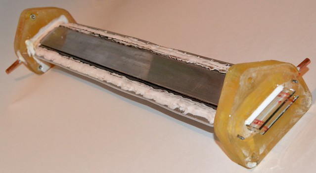
General view of the cuvette without mirror mounts. You can see the glass walls protruding to mirrors.
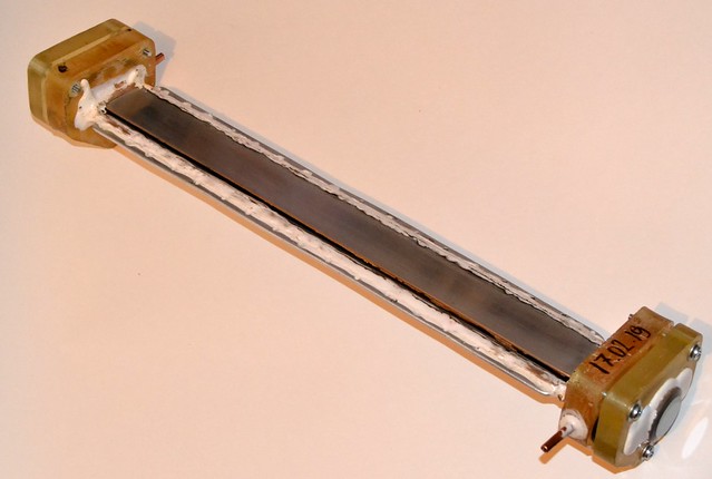
General view of the cuvette with mirror mounts. Last versions of epoxy mirror mounts were molded in 3D-printed molds.

Arrow designates the suck place.
The result is: the low molecular polyethylene is elastic enough for the
cuvette to survive the hot stress, but the glue itself fails under the working
temperature.
2-MM TUBE
26.03.2019
↑
Since a stable design (a one with on shell lifetime of three years at least)
made of affordable materials is still to be invented, the project has turned
back to experiments. What else a fully working but short-living thing is
suitable for?
Speaking about the experiments - the most urgent thing to know - is whether
the laser is able to endure the even more thin waveguide. With thinner
waveguide the heat sink conditions become better (it was told at the very
beginning of this web-report). However the closer the waveguide walls to each
other the more losses it applies to the beam, when it goes through the
laser channel. Rough but clear explanation of this fact is following: the
beam of light does not loose its diffraction divergency even when it
goes through a waveguide. Simply the walls of the waveguide continuously
reflect the spreading part of the beam back to its place - to the laser
channel. And the closer these walls are to each other, the higher is the
divergency of the beam, and thus the more reflection it takes on the way
from one mirror of the resonator to another. And the walls are not ideal
mirrors - just common window glass plates. It means that each reflection
adds losses. At some point these losses will overcome the gain and laser
will dim out. It means that there is some lower limit for the distance
between the walls of the waveguide. When this distance is below this limit
we have inoperational laser. And finally, if the power of laser rises at
first with making the waveguide more narrow and then goes to zero, it
means that there should be an optimum at some point. However to look for
this optimum is the task of far future. For the time I want just to find
the limits of operation.
So a laser tube has been built with the spacing between its glass walls
of 2 mm. It was glued by automotive silicone, simply due to the lack of
ideas of better glue among the affordables.


The most important result is that the tube appears to be operational.
Its measured output was 2.45 V by Peltier calorimeter readings. It means a
bit more than 15 Wt.
| The run conditions: |
| Resonator: |
Back mirror was a piece of some car rear view mirror with its
protective painting having been removed (leaving open aluminum
coating on a spherical glass basement, having its radius ~3 m).
Front mirror is commercial flat germanium mirror with ~30%
transparency |
| Mixture: |
CO2:N2:He = 2:7:18 |
| Mode: |
Gas Flow |
The optimum pressure was found to be 55-64 mbar (1.7-1.8"Hg); The surge
current was 250 mA when the ionization was applied to the anode of the
main discharge and both heat-sink electrodes. And when the ionization was
applied to the anode of the main discharge and to ONE of the heat sinking
electrodes the surge current reached 410 mA. The voltage drop across the
laser channel was ~1.2 kV in both cases. The output was ~15 W in the first
case and ~14W in the second. These levels of power could be achieved without
much of efforts.
Note that IONIZATION circuit POLARITY IS IMPORTANT!
The case here is similar to the problem of the flyback with voltage
multiplier. Nominally the current is alternating, but its shape is strongly
not symmetric, so only one of two possible variants of connection work
properly. The other variant gives much less efficiency.
In the process of looking for the optimal settings of pressure and
ionization intensity, the output power degraded smoothly and finally the
laser was able to give only 6 W independently to the pressure and type of
ionization circuit connection.
Opening of the laser had shown, that the output coupler was fouled badly
with products of burning of its mounting. The beam in the resonator appears
to be significantly wider than the mirror, and the stray parts of the beam
began to fry the mirror mount.


Further on the mirror mount was shielded by a piece of aluminum foil. The
metal reflects infrared beam almost perfectly and prevents burning of the
plastic.

Another incident - an alignment laser was damaged during the test runs.
Since the output optics of visible lasers does not usually transmit the
deep infrared radiation of CO2 laser, and because this optics is usually
highly tolerant itself, I've got a bad habit to not to protect the alignment
laser. This time it caused the failure.
A laser pointer was used as an alignment laser (not of a keychain type,
but of a pen type, powered by two AAA batteries). The collimator lense of this
pointer appeared to be made of some organic glass. And it burned out happily.
Note that it was not just unfocused beam of the CO2 laser. Actually the
beam was highly defocused since the laser pointer was placed far behind the
focal plane of ZnSe lense, which was used to gather the beam in the tests
on wood plank cutting.


If not pay attention to minor incidents and repairings, the laser just works.
The effects produced by 15W beam are very similar to the ones produced by 12 W.
The difference is barely seen by eye. Nevertheless I decided to put a small
video here:
20.05.2019
...The twisted approaches for the search of cheap and affordable replacements
for the laser mirrors are in the process... You could remember that it was
written above that the proper operation of the laser tube may be affected
by stray lasing between the electrodes, when they work as mirrors. (To be
more correct, this process does not affect lasing - the tube lases more
than perfectly - somewhere inside. But it becomes difficult to extract the
radiation out.) In this connection there appeared an idea to use some
aluminum plate as a kind of mirror. The plate should be inserted between the
glass walls of the cuvette, as the electrodes are. If the plate was not
made by hacksaw and filer, but if it was carefully cut from a (commercial)
extrusion (metal stripe or leaf), then at least one of its smaller faces
will be almost exactly orthogonal to its larger faces. And since the larger
faces will be hold tightly by the glass walls, it means that this smaller
face can be set to be orthogonal to the optical axis of the laser. It will
still require alignment in the transverse direction to the channel however.
5 pieces were cut from a commercial aluminum extrusion (a stripe, 20 mm wide
and 2 mm thick). The length of the pieces was 38 mm. The aluminum pieces were
put in an even stack and compressed
in vise. The face of the stack, that is formed by end faces of the aluminum
pieces, was then polished. It was supposed, that if the lasing can evolve
between the electrodes, that are not polished at all, it means, that there is
no need to bother with high quality polishing. The procedure was done by
a 15 min long rubbing with a felt disc, dipped into a 1.5 mcm grit polishing
paste. Yes the disc was rotated by a Dremel tool set to 15 000 rpm. The
resulting surface looks not very good indeed, but still it may look good if
we could see in the spectral range of CO2 laser wavelength. All roughnesses
are 20 times weaker for the 10.6 mcm wave than for the visible light.
Another deal is the shape. The irregular shape near the edges may be
detrimental. That is why the stack of 5 pieces of aluminum were polished
together, not a single one at a time.
The plate (with its polished face towards the frontal mirror of the
resonator was attached to the back mirror mount in such a way, that it could
be places between the glass walls of the cuvette and still was able to be
aligned at least in one direction.

With that kind of mirror the laser was assembled and got a test run. Some
difficulties were with the alignment. With this grade of polishing the
aluminum face gives extremely bad reflected spot of the alignment lased.
Actually the reflected spot consists of the diffuse halo only. No bright
core could be seen. So one can say that the alignment was made mostly at random.
Nevertheless the laser appeared to be able to operate with this grade
of mirror and with this grade of the alignment. The top achievable power was
in strong dependency to the initial position of the mirror, obtained as the
result of static alignment with the help of the alignment laser. This is due
to the fact that the dependency of the output power to the angle of mirror tilt
is nonmonotomic. Due to the multiple reflections from the waveguide walls this
dependency has multitude of local maximums and minimums, and when You are
aligning the laser during its run, using the calorimeter readings as the
reference, You may actually make things worse.
The top power, I got from the laser with this kind of mirror, was 1.5 Wt.
Here are the spots (on a fax paper) of the laser beam, taken when the laser
was operating at 0.4 Wt of power. Lets remember that the full spot hold be
2 mm x 30 mm when laser operates properly. I marked this shape as a stripped
line on the snapshots.
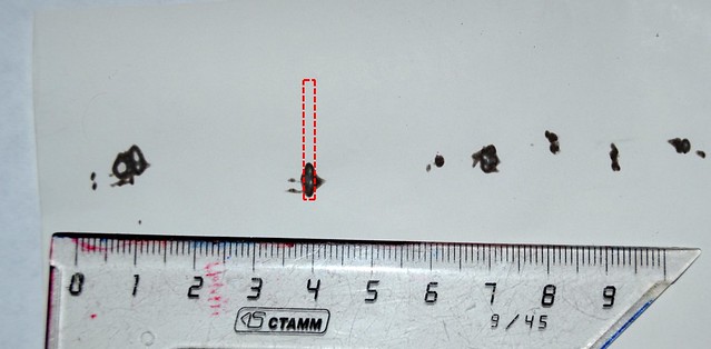
The thermal paper was hold manually. It explains the blurred spots and their "tails". One can see that the alignment is shifted to the right.
Here is the spot after the laser had been realigned, Here the output was
1.4 Wt. One can see through holes in the paper. As You can see the spot had
still not became continuous. There is the central powerfull part and weak
spots aside.

1.5 MILLIMETERS THICK TUBE
↑
Meanwhile a new cuvette was assembled with the spacing between its glass
walls equal to 1.5 mm (1/17 of an inch). It is a further step towards more
and more narrow waveguides.


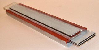

You can see that the design of the cuvette is kept intact. However one should
note, that this is the first cuvette, where not only the waveguide thickness
has changed. All previous cuvettes in this web-report had active area of
350x30xh mm (where h - is the spacing between the glass walls).
The new cuvette (with h=1.5 mm) has also another spacing between the main
electrodes. Now it is equal to 25 mm. I.e. the sizes of the active area are
now 350x25x1.5 mm. Note that: THE CUVETTE HAS BECOME SMALLER. Its heat sink
area was reduced by 17 percents. So with the same output its SPECIFIC load
is by 17% higher. Therefore strictly saying, the results obtained on this
cuvette aren't comparable directly with the results obtaines on the other
cuvettes.
The width of the active area was changed because I am still unable to elaborate
a way how to extract all the energy from the wide channel using small mirrors
only. I cannot say that I have no idea. On the contrary there are plenty of
them. But some of them require high precision parts, and hereby machining them,
not hand processing. Others require too much of work. (For example: a pair of
alignment plates at each of the ends of the tube. One of them is larger and
another one is smaller. The smaller one is to be placed above the larger one.
Too much of work, and complicated shape of parts - one needs not only to
preserve the vacuum tightness here, but also to keep the path of the beam
free of obstacles.) Even others require exotic tools (e.g. to make a collander
type mirror of an aluminized glass, one needs to sacrifice four diamond burs).
Yet another idea - to glue up the mirrors directly into the laser channel
during its assemblage stage - implies that one has skills of aligning during
assembling - not the simpliest work to do. And if the cuvette was assembled
with improper alignment there's nothing that could be done. Only to discard
the cuvette and to make a new one... And even if I personally will overcome all
the difficulties and finally make an exclusive thing, then what can I offer
to one, who reads this report with the aim to build his own sample of the laser?
Should I offer him to learn how to install and align the mirrors over years?
It's unacceptable.
These kinds of considerations have lead me to the conclusion, that I should
stop twist the weeds, and I should better make the laser channel to have
exactly the same width as the mirrors have.
The cuvette has finally been assembled, connected to the existing power
supply system, aligned and got a test run. The gas mixture was CO2:N2:He = 2:7:18.
The resonator consisted of the old good aluminized glass spherical mirror (still
the same piece of automotive rear view mirror, having the radius of curvature
of about three meters) and commercial germanium flat mirror with transparency
of ~30%.
The current results:
- The top pressure limit of operationability is 3.2" Hg;
- The optimal (for the time) pressure is 2.8"Hg;
- The surge current (the point of falling to arcing) @2.8"Hg - was not achieved;
- The surge current @3.2"Hg - 370 mA;
- Output power @p=2.8"Hg I=400 mA - 11.3 Wt;
- Voltage drop across the cuvette @p=2.8"Hg I=400mA - 750V;
Thus the new cuvette has the specific power per unit of heat sink cross
sectional area ~0.13 Wt/square cm. Compare it with ~0.149 Wt/square cm for the
previous cuvette. I hope that this is not the limit.
This hope is supported by the fact that the behaviour of the cuvette has
changed strongly in the comparison with the behaviour of the old one. It implies
that the true optimal values of pressure, mixture contents and ionization
strength are still to be discovered.
The first thing that has changed in the behaviour is the dependency of the
surge current to the pressure. In old cuvettes this dependency was rather smooth.
In this one it is abrupt: At 2.8 inches of mercury my power supply is just
unable to provide the current needed to cause arcing in the cuvette. At three
inches of mercury it is easy to hit the surge point. And at 3.2"Hg I was unable
to put any sufficient current through the cuvette without causing the bright
arc. One can say that the new cuvette is "harder" than the previous ones.
The second point is that the cuvette likes (comparatively) high pressures.
Generally it is not the first one, that behaves like that (e.g. see the note
from 09.01.2019). But I was unable to reproduce this feature with any grade
of stability. I.e. when I make, say, five cuvettes, one of them will operate
at 4.5"Hg, while the others - only at 1.5-2.5"Hg. What causes this difference
is still to be found out.
Generally the theory predicts that diminishing the thickness of the waveguide
will cause the rise of the pressure optimum. However this cuvette is the first
one having so small spacing, so it is still unclear whether its behaviour is
normal, or can be treated as an artifact.
27.05.2019
HELIUMLESS
↑
In comparison with the original variant here the thickness of the waveguide
has diminished by two times (1.5 millimeters vs 3 millimeters). Thus the
thermal resistance has diminished too. Does it mean, that the high temperature
conductance of the gas mixture is no more vital? Can we already exclude the
helium out of the mixture contents or not?
It was given a try.
A mixture of CO2:N2 = 2:7 was made. As usual the mixture was composed in
a car tyre (with the volume of ~ 20 liters) and before the mixing a small
droplet of xylene was put into the tyre (volume of the droplet can be
estimated as 1-2 cubic millimeters). With this mixture the laser got some
test runs. The results are given below.
- At the pressure of 1.2"Hg
The lasing threshold was 4 divisions (4div*46mA/div=184mA)
The arm of the milliammeter was easy to put onto the right border of the
scale (the surge current > 500 mA)
The laser output was 1.7-1.9 Volts by Peltier calorimeter readings (11-12 Wt)
The voltage drop across the cuvette was about 800 Volts
- At the pressure of 1.6"Hg
The lasing threshold was not noticed
The arm of the milliammeter was still easy to put onto the right border of
the scale and there was still no arcing (the surge current > 500 mA)
The laser output was lower however: 0.6-0.8 Volts by Peltier calorimeter
readings (4-5 Wt)
The voltage drop across the cuvette was closer to 1000 Volts
Further on the power of the external ionization was reduced. It was done by
the most straightforward method ever - by reduction of the voltage of the
power supply that feeds the output stage of the pulse generator. (From 220v
of net voltage to 200 v of net voltage.) Then a new runs were made:
- At the pressure of 1.2"Hg
The lasing threshold was still 4 divisions (4div*46mA/div=184mA)
The surge current was 7-9 divisions (320 - 420 mA)
The voltage drop across the cuvette was about 1100-1200 Volts
The laser output was up to 2.2 Volts by Peltier calorimeter readings (14 Wt)
With this level of preionization a run was made at the pressure of 1.6"Hg but
the laser was unstable and no reasonable results were obtained. Can only say
that it definitely lased.
Further on some water was added to the gas mixture. Water depopulates the
lower laser level of the carbon dioxide and makes the life of laser easier.
However if too much of water was added the quenching of the upper laser level
begins to be noticeable and it, instead of making things better, makes them
worse. To the automotive tyre containing the ready to use gas mixture it was
added a bit less than 0.1 ml of water (with a help of medical syringe). The
tyre was then put aside for a night to let the water go evaporate.
- The run
at 1.2"Hg gave the next results:
The lasing threshold was 3.5 divisions (3.5div*46mA/div=161mA)
The surge current was not achieved at full power (> 500 mA)
The laser output was 2.3 Volts by Peltier calorimeter readings (15 Wt)
The voltage drop across the cuvette was about 900 Volts
Even further an attempt was made to study the affect of atmospheric air.
To the remains of the gas mixture in the tyre (~8 liters) 300 ml of the
atmospheric air were added. Then a test run was made. Then again to the
remains of the gas mixture (~6 liters) the next 300 ml of air were added.
And a new test run was made. The results were generally the same as they were
without air. In both runs I could achieve more than 14 Wt of output and
in both runs I could achieve currents of more than 400 mA. The threshold
and voltage drop were also intact.
However: Without air it was easy to get arcing if the pressure was too high.
And it was hard to fall into the arcing if the pressure was too low (at least
until 0.5"Hg). On the contrary, with the air in mixture, the pressure range
of operation has got a lower border. The currents of above 350 mA could only
be achieved when the pressure was from 1"Hg to 1.3"Hg.
THE MAIN RESULT IS THAT 15 WATTS OF LASER POWER WERE ACHIEVED WITHOUT HELIUM.
The results are suspicious. We all got used to the fact that it is always
better with helium than without.
A fresh helium was purchased (yes, in a form of party balloons) and a fresh
portion of gas mixture was prepared. It was CO2:N2:He = 2:7:9 - mixture of
molecular gases mixed one to one with helium. Test runs were made at pressures 2", 2.5", 3".
The result is the next:
| Pressure |
Peltier Calorimeter Readings |
Output Power in Watts |
| 2"Hg |
2.9V |
18.5 |
| 2.5"Hg |
2.5V |
16 |
| 3"Hg |
1.3V |
8.3 |
Thus 18.5 W were obtained. The laser approaches 20 W closely.
Here is a video of how this laser saws a pencil. Do note - with the lead inside.
Interesting fact: the measurements are still made by an old good Peltier
calorimeter, not intended for such levels of power, but it is still operational
and gives reasonable results.
The calorimeter used here does barely differ from a one described in that guide.
The main differences: a prop was added to make its installation easier, and
shunt circuits were added to increase stability of readings in conditions of
strong electromagnetic interferences.
When this calorimeter was being assembled there was no intention to use it at
high average powers. So its linearity was tested up to 3 Watts only. And it
seemed obvious that it should show a strong non linearity at powers of ten watts
and above. At least due to the overheat of the small heat sink on the back
side of the Peltier element. And still the practice shows that it continues
to demonstrate good linearity even at powers of about thirty watts. It can be
proven at least by the fact that if one measures the output of several
laser diodes (3W rated) separately with this device, and then measures their
sum power simultaneously (total power of ~24W), the reading tends to coincident
with the sum of readings of separate diodes in range of +-5%. Amazing, but fact.
PHOTOSESSION
↑
I have finally bothered to take a photosession of the laser. The photos below
show it from different sides. A cuvette with 1,5 mm high waveguide is installed
there. In addition one can clearly see:
- Microwave Oven Transformer - power supply for the main discharge
- diode bridge
- U-shaped transformer of the auxiliary discharge generator (on two halves
of a flyback transformer)
- water heaters - the ballast resistor of the powerfull stage of the auxiliary
discharge generator
- ballast resistor of the main discharge (those green tube shaped things)
- adjustable stubs (a serious help for aligning)


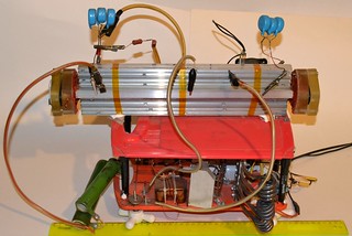
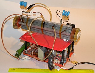
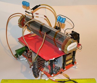


Note that the thing shown on the photos is almost the whole laser. To be
fully complete it needs (not shown on photos):
- A vacuum pump. Since the requirements to the vacuum are weak, the pump can
be small enough.
- A rectifying capacitor of the main discharge circuit (50 uF x 2 kV). Since
it can be assembled as a pack of electrolytic capacitors, it also can be
small.
- Automotive tyre or a bottle with gas mixture.
- And finally two variacs. One of them feeds the powerfull stage of the
auxiliary discharge generator. This provides a steep variation of external
ionization power. The other variac feeds the microwave oven transformer,
that feeds the main discharge. Usage of variac here allows to vary the
main discharge current and to approach closely to the limit of current,
where the discharge becomes unstable.
I.e. one cannot say that the laser 'is little' but a single man is more than
capable to carry it with all its accessories (including pump and gases).
The laser can be made even more lightweighted. Replacing the microwave oven
transformer by a mains voltage multiplier (by factor of 4) one can reduce
the weight. In addition in this case there will be no necessity in the separate
rectifying capacitor in the main discharge circuit. One can also exclude
the variac of auxiliary discharge feeding. It was included for researches only
- to investigate how the laser behaves with different levels of preionization.
In most cases the laser is happy to operate when the plug of the auxiliary
discharge generator is plugged into the 220v mains directly.
9.01.2020
The arrival of New Decade was celebrated by tests of a new laser tube. The
gap between the walls of the waveguide became 1.0 mm. The spacing between the
electrodes in the new tube was 25 mm. The active length 350 mm. A full length
of the laser "mirror-to-mirror" was 400 mm.
I didn't expect any increasement of the output power from the new tube. The
output is already limited by the footprint of the laser channel and by the
heat conductivity of the glass walls. The laser has already reached the
conditions, when the temperature drop in its glass walls is near to their
limit by the thermal crackling. The temperature inside the laser is also too
close to the limit of gas operationability. So without using of much thinner
glass walls (or much larger cuvette) one should not expect any sufficient
rise of power.
From the other side the reduction of the waveguide spacing could bring some
increasement of the working pressure and some stability of the discharge on "bad" gas mixtures. ("Bad" here means the mixtures that contain large amounts
of impurities and particularly oxygen.) I.e. one could hope that the laser
with a narrow enough waveguide would be able to operate on mixtures of air
with carbon dioxide when being pumped out by a reversed car tyre pump or
fridge compressor.
Here are the photos of the new cuvette:
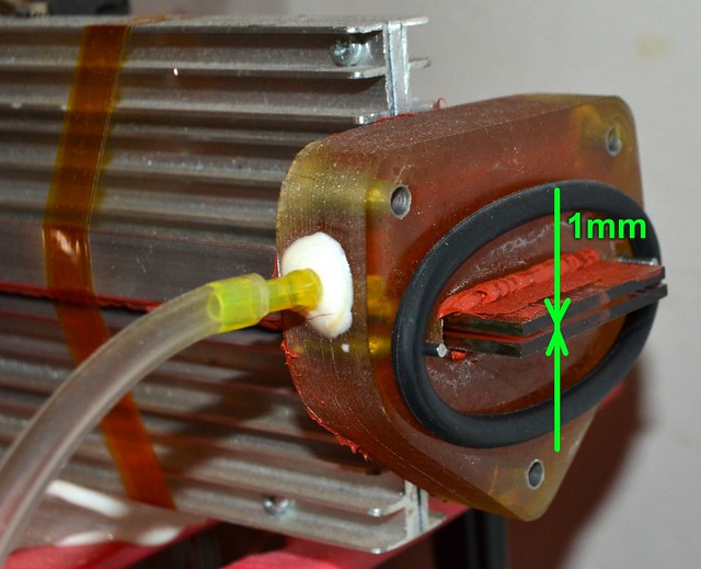
Its power supply unit and mirrors of the resonator were kept unchanged. The
cuvette design is also typical - aluminum side electrodes, being glued
between two glass walls by a silicone caulk. There glass walls also carry
some aluminum plates functioning like thermal interfaces and preionizer
electrodes. Large aluminum air heat sinks are set onto a thermal paste above
those plates.
The first obstacles were met at the alignment stage. In comparison with the
previous variant the thickness of the waveguide is smaller only by 1.5 times
(from 1.5 mm to 1 mm) but the difficulties have risen greatly. A beam of
common (red) alignment lasers appeared to be unable to wade through the
millimeter wide slit without touching its walls. As the result there are
many false reflections out there. And there's no way to comprehend which
spot is the correct one and needs to be directed to the orifice of the
alignment laser. After a pair of runs with the false alignment, when the
laser had refused to give anything higher than 2 Wt, it was decided to make
the alignment using a violet laser.
It is well known that the diffraction divergence of a laser beam grows in
direct proportion to its wavelength and in inverse proportion to its diameter.
One cannot increase the beam diameter here - it would bounce over the walls
of the waveguide. One cannot decrease beam diameter also - it would diverge
stronger and finally will hit the walls too. When the beam bounces over the
glass walls there appear plenty of false reflection an the alignment becomes
hard to perform or even impossible.

The wave of some violet laser (405 nm) is 1.6 times shorter than the wave of
typical alignment laser (red, 650 nm). The achievable divergence is 1.6 times
lower too. And the fact that similar cuvette with 1.5 mm spacing could be
aligned with red laser lets me expect that a millimeter sized cuvette will
be able to be aligned with a violet beam. It's not a Panacea however, but
with the violet laser the alignment is really easier.

Finally the laser was aligned (to the best extent I could do) and got a run
on a mixture of CO2:N2=2:7. At 1.5 inch of mercury pressure the laser easily
did 12 Wt (by calorimeter readings). An attempt to increase the pressure was
not successful however. With pressure rising the output drops quickly and
there is no lasing when over 2"Hg. Surprisingly the discharge is stable at
these pressures. No fall to sparking and arcing in all the range of pressures,
where my power supply unit can provide a reasonable current (up to 3..4 inches).
I was unable to obtain arcing even with cutting the voltage, that feeds the
preionizing generator, by half (from 200 V RMS to 100 V RMS).
The discharge is beautiful. The current is about 0.5 Amp (~700 W of applied
power). AND NO LASING!
In principle the situation is explainable. Thinner waveguide has higher losses
and to compensate them one needs more gain. The gain can be increased either by
higher energy input or by improving of amplification properties of the medium
(particularly its emission cross section). The energy input cannot grow any
more, because of the heat limit of the cuvette. The glass walls with their
current thickness are near the limit of their heat sink capabilities. As for
the gain properties of the medium, they can be easily improved by lowering
the pressure (exactly what we see in practice) but it conflicts with the
fact, that this cuvette was created in try to increase the pressure, not
to lower it. Another way to enlarge the gain without overheating is to
rely on QCW mode, i.e. when one feeds the laser with powerful and short pulses.
But I cannot say that this way will be clear of problems. And additionally,
this is the task for TEA lasers, not for this one.
So the diminishing of the thickness of the waveguide had not brought the
desired higher pressure of operation. Let's see how'bout "bad" mixtures?
Further on the laser was tested on mixtures of air with carbon dioxide. In
the table (tables) below there are the results of measurements of the
dependence of output power to mixture contents and to pressure. The
content is expressed in volumetic parts. (Let me remind You here, that a
good reversed fridge or tyre compressor can reach 2..2.5 inches of mercury
and an average one can do only 3..3.5 inches.)
| mixture CO2:air=1:1 |
| P "Hg |
Wout (Watts) |
| 0.6 |
5.76 |
| 0.9 |
8 |
| 1.2 |
7.04 |
| 1.5 |
4.096 |
|
| mixture CO2:air=1:2 |
| P "Hg |
Wout (Watts) |
| 0.6 |
6.1 |
| 0.78 |
10.6 |
| 0.9 |
11.5 |
| 1.2 |
8.3 |
| 1.5 |
9 |
| 1.8 |
1.3 |
|
| mixture CO2:air=2:7 |
| P "Hg |
Wout (Watts) |
| 0.6 |
8.8 |
| 0.9 |
10.2 |
| 1.2 |
11.5 |
| 1.5 |
11.8 |
| 1.8 |
4.1 |
|
| mixture CO2:air=1:4 |
| P "Hg |
Wout (Watts) |
| 1.1 |
12.2 |
| 1.3 |
12.5 |
|
| mixture CO2:air=1:5 |
| P "Hg |
Wout (Watts) |
| 1.1 |
7.4 |
| 1.2 |
10.9 |
| 1.5 |
10.6 |
| 1.8 |
9.9 |
| 2.1 |
5.1 |
| 2.4 |
0 |
|
| mixture CO2:air=1:8 |
| P "Hg |
Wout (Watts) |
| 1.5 |
9.6 |
| 2.15 |
9.3 |
| 2.4 |
0.6
|
|
One can see that gas-air mixtures allow to get the same power as gas-nitrogen
ones. One can also see that the top pressure of operationability rises with
increasement of mixture dilution. However the top power, achievable at optimum
pressure, becomes lower. It looks like at dilutions of 1:12..1:15 the laser
could operate at the pressures obtainable by some DIY vacuum pump, but the
output would not make us happy (5..6 Wt in better case).
February 2020
50 mm WIDE TUBE
↑
If we look at the previous results, it comes out, that diminishing of the
waveguide thickness from 3 mm to 2 mm and from 2 mm to 1.5 mm gave stable
improvement. Improvement of power, stability and tolerance to contaminants
in the gases. Generally it improved the pressure too, however for now the
individual specialties of tubes do affect the operational pressure more
than their geometry does. Further decreasing the gap from 1,5 mm to 1 mm
have improved neither output nor stability. Only the alignment procedure
have become evil hard to perform. (Maybe the tube with 1.0 mm waveguide
was potentially more powerfull than the one with 1.5 mm waveguide, but the
hardship of its alignment made it impossible to realize that potential.) Finally it was decided that 1.5 mm is the optimal thickness of the waveguide.
Where to move further? The optimal thickness has been determined already. To
increase the tube's length means much more current and much more preionization.
And hence it means to rebuild the whole system including the power supply and
the pulsed ionization source. What's then? Yet again to try to increase the
width and hope to extract the light somehow from the wide resonator using
small mirrors?
A tube has been build having the discharge width of 50 mm (electrode-to-
electrode). The thickness of the waveguide was chosen to be 1.5 mm (wall-to-
wall). The walls of the tube are still glassmade, the glass is 2 mm thick.
The length of the active part is 350 mm. Full length of the resonator (mirror-
to-mirror) is 400 mm.
It was possible that the cuvette would not sustain the atmospheric pressure
being so wide: (35 x 5 x 1 = 176 kilograms of pressure force), however the
thermointerface plate (just a flat aluminum plate. 350 x 50 x 2 mm sized,
having been glued upon the glass) makes the strength of the cuvette to
increase. Lemme remind that the gluing of the thermointerface plate as well
as the gluing of the whole cuvette is to be made by an automotive silicon
caulk.
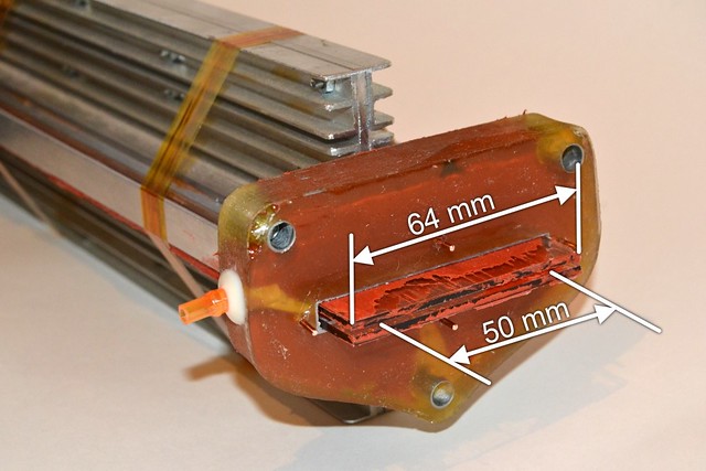
As the result the cuvette endures evacuation perfectly. Since the discharge
width has grown, the voltage drop across the cuvette has grown too. With the
mixture of CO2:N2 = 2:7 at 370 mA of pumping current the voltage drop reaches
1.7..1.8 kV. Almost twice as much as it was for "narrow" cuvettes.
First of all the cuvette was tested in a "common" type of resonator - the one
consisting of a concave aluminum mirror with radius of curvature of 3 meters and
a flat semitransparent one with transmittance of 30%. The active part of
resonator is limited by the diameter of the output coupler and is equal to
25 mm. In this case the cuvette gave 12.6 W of power @ CO2:N2 = 2:7 and pump
current of 370 mA.
Further on the laser was equipped with a hybrid output mirror. The general idea
of the mirror is just the same as it was in the very first variants of this
laser: the semitransparent mirror is enframed by a metal mirror having an
appropriate hole. However
the practical design does differ. Instead of the full round concave mirror
that was used earlier, here I use two flat mirror slats. When being glued
all three parts of the mirror (two metal coated slats and the semitransparent
one) are aligned as so the reflections from them form a common spot as if it
was a single mirror.
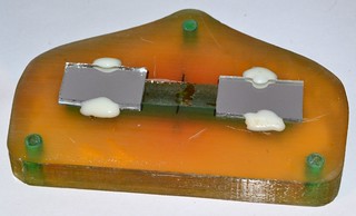
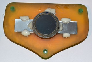
Literally the first try with the new mirror gave 18.3 W of the output power.
But in the first run the mirror was fried up and further i was unable to get
more than 10 W from out there.


In order for the mirror not to burn in a powerful beam the aluminated slats
were modified. Their edges became skewed so that the glass body of the thing
should be perfectly screened by the aluminum layer:

The run with this new mirror allowed to register the output of 26 W. However
the mirror had melt again.

Finally I fell to use some hand polished aluminum metal plates, being cut from
an older mirror with holes. As the result the
mirror stopped to burn out, but the output became modest too: 19-20 W.
- Laser technique and technology. In 7 books. Book 2: Engineering basics of
technological lasers design: High school textbook. / V.S. Golubev,
F.V. Lebedev; Editor: A.G. Grigoryants. - Published: Moscow, Vishaya shkola,
1988.
- A.A. Kuznetsov, M.Z. Novgorodov, V.N. Ochkin, et al. Compact Slit-Type
CO2-laser Excited by non Self Sustain Direct Current Discharge, Maintained
by Short Pulses. Preprint of Physical Institute of Academy of Sciences,
named by P.N. Lebedev, N15, Moscow, 1997.
- V.N. Ochkin. Waveguide gas lasers. M.: Znanie, 1988.
- V. J. Vitteman. CO2-laser. (russian edition) M.: Mir. 1990.
ISBN 5-03-001351-2 (rus)
ISBN 3-540-17657-8 (eng) by Springler-Verlaf Berlin Heidelberg, 1987
<< HOME PAGE |


