Within this guide we shall learn how to make a small lamp pumped dye laser, and it will be made of only affordable resources (the concept of
" the-laser-from-a-general-store"). Ought to warn You in advance that this laser won't cut
things or either burn holes (however it is fully capable to damage a webcamera). It shines but does nt burn. And newertheless its output is far more powerful than the one of any dye cuvette being pumped by any nitrogen laser of any reasonable size.
Moreover this laser is very small. Even the described here sample (not yet fully optimized) can easily be held on a palm.
And it can be designed to be even smaller. In relation to the cost and affordability this laser concedes slightly only to
the famous air filled nitrogen laser.
On the other hand technically this is a full value laser with mirrors, alignment plates, with pumping lamp and active medium. It is understandable that it has rather complex design
and requires more experience for its creation and tuning.
apparata:
- High voltage power supply or an electric stungun
- laser pointer with red beam
- laser pointer with green beam
- 3-5 ml medical syringe
TOOLS:
- metal cut hacksaw
- office scissors
- drill and bits (of 2 mm, 3 mm, 4 mm, 5 mm and possibly 6 mm)
- damond (or alumina) cutting disc on a spindle suitable for Your drill
- a ruler
- a caliper
- some drawing tool (i.e. marker)
- soldering iron (with corresponding solder alloy, colophony and flux for aluminium)
- vise, screwdriver, pliers and other hardware tools
- hot glue gun (and of course some rods for it)
- office paper puncher
MATERIALS:
- xenon lamp from a small and cheap (soap-box) photocamera; the lamp should have ~3mm bore or less
and it should have the spacing between the electrodes not less than 25 mm. (Here a Chinese lamp was used.
It was marked as L-3230 (xenonflashtubes.com)) There are many types of them.In general the longer and thinner lamp You use, the better chances of lasding You have.
However it's senseless to choose a lamp with bore less than 1 mm in diameter.
- glass tube with external diameter 2..2.5 mm and 1..1.5 mm bore (there exists a robust resource of such tubes:
it is CCFL lamps usually used for TFT-monitors illumination. The glass tubing will be used to make the active cell. As it is shown at the end of this guide, one can use a piece of rod from some ball pen, provided that it is narrow enough and made of thin transparent plastic. However the output will be worse.
- Metal pipe having the external diameter of 5 mm (for hose connectors)
- Two pieces of 10 mm thick plastic. Each of them not smaller than 20x20mm. They are needed
for alignment plates. The requirements for their material are rather contradictive. From the one side the material should be stable under the affect of the dye solution at least for several weeks, from the other side it should be adhesive enough to be glued, from the third side it should be easy to work with, from the fourth side it should be rigid enough to keep the alignment...
It was found out that organic glasses are unvaluable for this purpose. They crackle after extensive exposure to ethanol or isopropanol. The type of the organic glass (plexiglass perspex etc..) does only
affect the lifetime, wheteher it be a hour or a week.
Kinda positive results were obtained with thick textolite and with epoxy molds
(the latter You can make Yourseleves just by filling some suitable vessel with epoxy resin and curing it there
- o-rings for 2..2.5 mm diameter.
The internal diameter of the o-rings should be equal or slightly less than the outer diameter of the
glass pipe used as the laser cell body. The rubber o-rings are used for tightening the glass tube in the places of its entrance to the alignment plates. The o-rings of such a size are rather rare and there are only a few things that can replace them. If You are having difficulties with obtaining so
small o-rings, You can try to cut the rings from a rubber leaf or either to cast them using some RTV silicone.
You can even try to secure the cell body by gluing it with a hot glue but this gives only a temporary solution.
Keep in mind that the humankind for over than 2000 years long makes vain tries to fix the waterpipe leakages and haven't got anything better than the poor o-rings yet.
- Microscope slider
It will be used as a material for windows. One can use any thin and flat glass with high transparency
(without any bluish or greenish color)
- a flat mirror with aluminium reflecting covering.
The mirror is not necessary to be "first surface". A piece of a good quality make-up mirror would suit too.
- A flat dielectric covered mirror from a DVD-drive.
- Screws M2x10 with suitable nuts. 6 pcs minimum. It is possible that You will want to use them not
only for the alignment plates but also for other attachements. In this case You will need more than
six small screws.
- A piece of an aluminium angle extrusion 25x 25, 50 mm long (for the ender props)
- A piece of an aluminium angle extrusion 20x 20, 70 mm long, two acorn nuts (not smaller than M10), and correspondent bolts. This husbandry will be needed for making a spark gap. In principle it
can be open, but it is better to choose some plastic part for its housing - it will greatly reduce the
noise troubles.
- A plastic basement suitable by its sizes for placement of all the laser. The basement should be also rigid
enough to keep the alignment. In my case the laser was able to be assembled on a 150 x 30 mm rectangle.
The basement thickness was choosen to be 10 mm. Most probably You will be able to make things even smaller.
- Some aluminium foil. As usual in the high voltage technique - the thicker the better. (In the reasonable
limits of course.)
- Mylar foil for making the capacitors (if You are going to use commercial capacitors the mylar foil will probably still come handy, e.g. for insulation weak places of Your construction.)
If You use single layer, use 125-150 mcm thickness. If Your mylar is thinner, it is better to use several layers then.
- An alcohol (ethanol or isopropanol, methanol or even glycerol). It is needed
for making the laser dye solution. The most robust of them is ethanol. It is nontoxic and rather non agressive.
However it is rather hard to obtain.
- Rhodamine 6G.
Certainly this is the main working dye. There is no adequate replacement for it.
One can obtain the Rhodamine 6G by buying over the internet or by checking any available peremanent red markers for Rhodamine presence.
SCHEMATICS OF THE LASER
↑
The design of the laser cell is shown on the Figure 1.

Figure 1. The design of the cell of the small sized lamp pumped dye laser.
1 - windows
2 - props
3 - sealing gasket (o-ring, for the sake of clear view the similar gasket on the left part
of the drawing is omitted)
4 - alignment plates (window-keepers).
The electric scheme of the laser is shown on figure 2.

Figure 2. Electric circuit of the small sized lamp pumped dye laser.
Cs - storage capacitor, a handmade mylar foil rolled-up capacitor 16 nF x 10 kV
Cp - peaking capacitor - a handmade mylar foil rolled-up capacitor rated to 500...1000 pF.
SG1 - low inductance air filled spark gap of "ball-to-ball" or "ball-to-plane" types. It should trigger up at the voltage of 10 kV.
Rb - ballast resistor rated to ~ 1 MOhm, Rs - shunt resistor (provides integrity of the circuit for the direct
current when the lamp is still cold. The shunt resistor value should be 1..10 kOhm and it should endure
the applied voltage of 10 kV.
Lamp1 - xenon flashtube having the interelectrode spacing of 25-40 mm and bore of ~2..3 mm
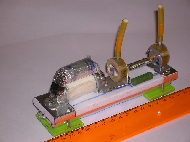
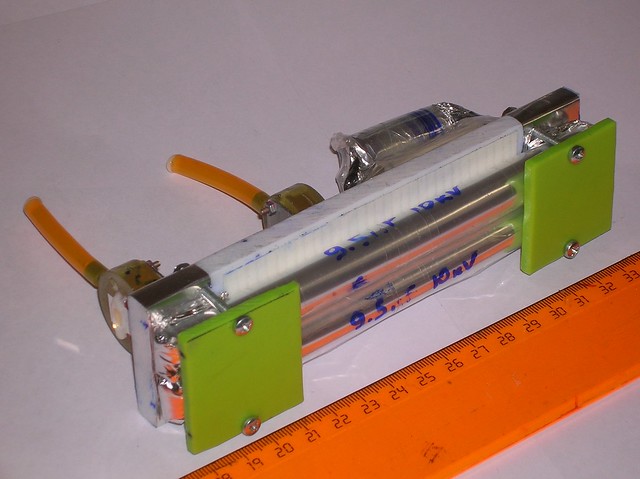
The arrangement of the laser is shown on figure 3.

Figure 3. The arrangement of the laser.
Spark gap SG1 is placed near one of the ends of laser cell. The peaking capacitor Cp is
attached directly to the spark gap. The storage capacitor is placed under the basement.
Such an arrangement was choosen in try to provide the smallest inductance of the pulse forming network.
MAKING THE LASER CELL
↑
The sequence of making and assemblage is generally the next: first of all we make props,
then the alignment plates, then we drill holes in the alignment plates together with the props
(both for the attachment and for the glass pipe), then finalizing the alignment plates,
(enlarging bore from the front side, and adding the hole for hose) then gluing the hoses in,
gluing the windows, screwing the alignment plates to the props, marking the basement, setting
the props on it, and only after all this we' ll measure the necessary length of the glass tubing
and cut it down. The narrow glass pipe is too rare to allow the another way of action. If You
have cut it beforehand, further on the errors will accumulate and cause that the previously cut
piece won't suit.
Let's begin. Cut two pieces from the 25 mm wide aluminium angle stock. The width of the pieces will be
25 mm so that it will have a square base


Process the plastic pieces intended to become the alignment plates so that they fit the props by their sizes.


Mark the places of future holes on the plastic plates. There will be four holes, the central one
for the glass tubing and three side ones for the holding-alignment screws.
The central hole should be close to the center of the square of the prop shape.
And in any case one should try to keep the holes in both of the props to be at the same
height from the basement.
The places of another (three) holes intended for the holding-alignment screws is not so
critical. However one should keep in mind that they should not be too close to the axis. It reduces
the arm of the alignment and therein its precision drops down. The holding-alignment screws are
oftenly plased in the vertices of equilateral triangle. However it is not necessary.

Drill the central holes in the pairs of prop+alignment plate. Use some clamp to
attach the alignment plate to the aluminium angle prop and drill a 3 mm hole
(to be more precise the diameter of the hole should be 0.2..0.5 mm larger than the
outer diameter of the glass pipe used for the cell's body. However the diameter of
the hole must be smaller than the outer diameter of the o-rings being used.)

Now the alignment plates may be attached to the aluminium props by means of a screw and nut
pair going through tje central hole. This will simplify the drilling of the remaining holes.
Having attached the parts drill the holes for the holding-alignment screws.


Its time to enlarge the front entrances of the central holes in the alignment plates.
The front side of the central hole (channel) in the alignment plates (the place where the
windows will be glued upon) should have a bit larger diameter than the other part of this hole.
The reason for this is due to the fact that in the process of gluing the shores of the pit will
be contaminated with glue, and if there is no expansion foreseen, the contaminations will break the beam path.
The more perfectly You can glue the windows and the narrower is the contamination area,
the less expansion of the hole You can make. At early tries choose the diameter of the expansion pit
to be ~5 mm.

Now You can drill the side holes for the nipples. The nipples should fit the pipes being used.
Among the automotive glass washing systems and among the aquarium equipment almost the most sppread
are pipes having bore slightly narrower than 5 mm. If targeting for their use one should choose
the nipples diameter to be 5 mm.
The nipples are easy to be made of tubings from a telescopic antennas (the telescopic antenna is
literally the treasure chest filled by many good tubes) or either one can use a cylindric part
of some extractable rivets body.

At this stage one should glue the nipples(hoses) into the side holes in the alignment plates.
Good results can be obtained using an epoxy resin (JB-weld). A bit worse is hot gluing
(using a glue gun with black colored rods). One may also glue the nipples by means of
some RTV silicon gum, but the curing process may take several days.

The next step is gluing the windows. Same as with hoses one can use an epoxy resin, a hot glue,
or an RTV silicone here. It should be mentioned that I still know no glue that could endure
the alcohol solutions along a very long time.
Epoxy resins flake off in three days - three weeks depending on their type. The blak hot glue rods
are able to hold the windows up to two weeks, RTV silicones live from two weeks to three monthes,
again depending to their type. Acrylic photocurable polymer lives froom one to two weeks under
the affect of alcohols.
One should get that such a laser is principally the subject for regular repairs.
The only alternative is to set the windows upon the fair rubber gaskets with the use of pressing flanges.
But this solution leads to great complication of the whole design and its assemblage. Since that complexities
may prevent You from making the laser at all, I recommend You to stick to the glued windows for the first time.
Before gluing the windows upon the plasic plates be sure to rub the windows for the most clean state You can reach,
After the windows have been glued You will loose the access to clean them from the inner side.

When the alignment plates (window keepers) are ready, one should screw them up to the aluminium (angle) props.
with a help of the holding-alignment screws. Then proceed to the markup of the basement.
The props are to be positioned so that the xenon flashlamp could be placed between them with a certain
excess. Too much of excessive length is bad because the non-lit part of the dye solution can do nothing
usefull, it can only absorb the light being amplified and can only make the laser to be less powerfull
and more critical in tuning.


Aside of that the props should stand being parallel to each other, and the line, that connects the centers
of their central holes (future axis of the glass tubing) should be perpendicular to the planes of the
window keeping plates.
A bit more experienced builders will make the markup readily having set all the parts into a beam
of an alignment laser. For the less experienced ones I'll recommend to use a drawing triangle or a caliper here.

After the ending units of the laser are installed one can measure and cut the main glass tubing.
Take a piece of a glass tubing having 1.5..2.5 mm bore (or an old CCFL lamp from a dead TFT monitor),
measure and cut a piece having the necessary length. The length of the piece shoul be 1.5..2 mm less
than a window-to-window distance in the assembled laser. I.e. when the laser is assembled the ends
of the glass tubing should be close to the windows but still not in contact with them.


If You are using a piece of CCFL lamp, the internal surface of the tubing needs to be washed from
the luminophor. One can do this by pulling a piece of wet cotton trhough the tubing by means of thin
copper wire.
Install the glass tubing and tighten the holding-alignment screws slightly.
Fill the laser (at this stage You can use some clean water) and check for leakages.


If the leakages are present fix them. If not, proceed to the installation of the lamp.
Before the installation of the lamp be sure to dry the laser.
For the simplicity the front and back props of the laser (aluminium angles) aslo
bear the functions of the lamp terminals. And because the storage capacity is usually placed under the laser
the necessary path for the electric current is made by wide strips of aluminium foil wrapped around the
basement just under the props. Those strips are connected to the lamp leads by means of wide triangle
pieces of aluminium foil.
The props under the voltage do reduce the safety of the laser. Since that all the operations with the laser
(including the assemblage and alignment) can be performed only and after the laser has been completely and securely
discharged.
In Your own design You can avoid the props being under voltage. In order to do this You will have to elaborate
some other way for conducting the current. Keep in mind, however that the
conductors should have the lowest possible inductance and reasonably low resistanse.
Put the lamp close to the glass tubing of the laser cell and wrap them by two turns of an
aluminium foil (shining side towards the inside). Fix the foil by a strip of a sticky tape.


Not necessary to achieve too tight contact between the lamp and the glass tubing. The gap of 0.5..1.0 mm
is allowable (and it even helps to reduce the stresses).
Solder the leads of the lamp to the current cunductors. If the conductors are made of aluminium,
the wonderfull flux for aluminium soldering will help You out. (In Russia it is marked as "FTKA" flux.
Sorry for I'm unable to tell You the mark of the aluminium flux for Your particular country.)

Thats all. The laser cell is ready. If You already have got a suitable low inductive battery of
capacitors and a suitavle spark gap, then You are ready to align and test the laser.
Further on, however, lets proceed, like You have no capacitors and spark gaps.
MAKING THE CAPACITORS
↑
The dye laser requires a very fast light pulse for its pumping. There is no practical perfection
on this way. Just the shorter is the pulse, the better. Thereafter the capacitors are to be low inductive.
Despite the fact that the laser appeared to be able to operate using the home-rolled capacitors of
the "shirt" type (occasionally here will be a guide how to roll up them too) those are not the best.
The storage capacitor we'll make of "candy" type capacitors. Their inductance is usually smaller.
They were named due to their look. The roll of dielectric film with outstanding ends of foil resembles
a candy if the foil endings are twisted and crumpled.
In order to roll a candy type capacitor rated to approximately 10 kV 8 nF
one needs to get two strips of mylar film 150 mm wide and 700 mm long and 125 mcm thick
(one may use thinner film stacked into several layers) and two strips of aluminium foil.
The sizes of the aluminium foil strips should be choosen to have such a value that allows the rims to be large enough
as shown on figure 4.

Figure 4. The mutual position of the metal foil and dielectric film for the capacitor assemblage.
When two such pairs of the foil and film strips are put togeteher they form a planar capacitor
having the covering area of metal plates being 50 mm wide and having 50 mm rims at both sides.
So large free space for the rims is due to the fact that in the rims area at least one side of the
dielectric is covered with metsl, i.e. there are the fulfilled conditions for the sliding discharge
development.
Further on this planar capacitor sould be rolled up to form a tube for the compactness.

Dependently to the tightness of rolling the capacity value will be in range from 4 nF to 9 nF.
In addittion to the common way of folding (the method described above, see fig 5a) the another way is possible.
In this case the foil is put into the folded strip of the dielectric (see fig 5b). In theory the second way
is better because it allows to use smaller rims. However in practice the fold strongly bugs during rolling
(it makes waves and ripples and displaces the metal and dielectric). As the result this design appears to
be not smaller than one bade by the common way (provided that one appears to be able to roll it up at all).
However if You feel strong to overcome all the difficulties, be sure to try both designs of the capacitor.

Figure 5. Different layouts of the capacitor before the roll up.
In the reality the good rolling can bother even in case of the first (common) design.
So it has sense to consider a use of commercial capacitors. If You choose the ceramic (doorknob)
capacitors, keep in mind that due to the non-linearity of the electric permeability the еnergy
stored in ferroelectric materials is usually by 20%..30% less than the energy stored in the
common dielectric films, provided that the charging voltag and capacity are the same.
So if our laser exploits two film capacitors 8 nF each, then when replacing them by a batterry
of ceramic capacitors, be surew to increase the overall capacity to 20 nF.
It should be also reminded that the capacity values choosen here (16 nf for film ones and 20 nf for ceramic ones)
represent the optimal value. The threshold of the laser (when the
rhodamine 6G solution is clean enough) can be reached at 2..3 times lower energy.
MAKING THE SPARK GAP
↑
This laser uses uncontrollable and untunable type of the spark gap. For the simplicity and
affordability the spark gap utilizes the common air as the dielectric gas. Te voltage of the spark gap
Self triggering should be 10 kV. For the air with the pressure, temperature and humidity typical for the place
where I live it corresponds to the spacing between the spark gap electrodes being equal to 4 mm (provided that
the electrodes are spherical or have the shape of a part of sphere and have the radii about 5 mm)
In Your district it is possible that the spacing between the electrodes will require some correction.
Except the triggering voltage another main requirement for the spark gap is its lowest possible inductance.
However it is a bit of overkill to use here a multi-gapped rail switch. On the other hand avoid to use
pin-to-pin spark gaps and try to use the wide conductors to connect the spark gap to the circuit.
(At those puse durations due to the skin-effect the electric current does not want to enter the depth of
the metal. Terefore the tube shaped and the full cylinder conductors are equivalent, and the wide strips
of aluminium foil usually appear to be more effective than bulk copper bars.)
Avoid to use polished spheres in the spark gap. This increases the bias in the self-triggering voltage
and this can lead to failure of Your so precious capacitors.
When keeping in mind all the said above You have a wide space for creativity.
The photos below sow the example of the sequence of spark gap creation.
The electrodes are made of two M8 acorn nuts. The leads are made of aluminium angle extrusion pieces
20x20 mm each. The housing for the spark gap is made of a piece of plastic tube 20 mm in diameter.
The length of the tube piece shood be appropriately choosen to provide 4mm of the gap between the rounded heads of the acorn nuts.
All the thing is sealed tightly with a hot glue (glue-gun).


Variants


MAKING THE DYE SOLUTION AND REFUELING THE LASER
↑
The laser works on solutions of Rhodamine type dyes in different alcohols.
With the low gain dyes (fluorescein, coumarines) this laser is inoperational (for the present time).
If You have a green laser pointer there exists a very simple rule for choosing the correct dye
concentration of the rhodamine-like dyes:
- THE DEPTH AT WHICH THE GREEN LASER POINTER BEAM FADES IN THE DYE SOLUTION SHOULD TO BE EQUAL TO
THE RADIUS OF THE GLASS TUBE USED AS THE BODY OF THE DYE LASER CELL.
Since the bore of our tube in our laser is 2..2.5 mm, the depth of the green beam fading should be
1..1.25 mm. Practically it looks like a bright fluorescent core with the size of a small matchhead.

Simply add the alcohol to the dye untill You gave the picture shown above.
If You have no green laser pointer the things gonna be more disgusting. One can
look about the thickness of the fluorescent layer when the daylight shines to the vial with the solution from the above.
The thickness of the layer should be from a half to a complete diameter of the tube used in the dye laser cell.
Defining the proper concentration by the thickness of the fluorescent layer requires
much more skills and experience.
If You are making Your first dye laser, the advise is to keep the sample of the dye solution as
soon as You got the lasing. Ewen if the solution "turns sour" (i.e. if it becomes useless
for fueling the laser) it will still be usefull as a sample for comparison with freshly made solutions.
For those purposes it can serve You many years.
The alcohols suitable for creation the laser active solutions are the next:
- methanol (rather hard to obtain; it is used as a component of the airplane models fuel
so You can find it at shos for airplane modellers)
- ethanol (simplier to obtain than the methanol, but in most countries it is still not available freely)
- isopropanol (freely available in drugstores, in general stores as glass washing aid and in radioelectronic
stores as general solvent)
- glycerol (not necessary water free) glycerol contaminated with some water is available in drugstores
and it can be readily used for the described laser
One should note that the methanol is rather strong poison. Use it with care and good ventilation.
Ethanol is nontoxic but can cause so called "drunked" state. Isopropanol is slightly toxic.
Dont drink it. However there's no information about heavy poisonings with it. Glycerol is harmless, however it is too viscous
and You can not use the dye circulation mode with the cell bore equal to 2 mm. Another difficulty with the glycerol
is the complications with filling the laser - it is wery hard to get the bubbles out.
The vodka (40% of ethanol in water) appeared to be unusable as the solvent in this laser (because the gain
is lowered due to nonhomogenious broadening). There was some success with lasing this laser usin the dye solution
in water with some detergents (simply saying: with soaps). However the available detergents, the laser has been
checked with, mostly give laser inactive solutions. And those rare ones that agreed to operate provide the lifetime of the
solution only of the order of tenth of minutes (even not hours).
The fueling process of the laser depends to whether You use a circulation pump or not.
If You use an external vessel for the dye and the circulation pump, just fill the vessel with the dye solution and turn
the circulation on. The buubles will go away with the dye flow themselves.
If You have no circulatiopn pump the filling of the laser is a bit less trivial. The key moment of the filling process
is to achieve absence of the bubbles in the laser cell. Use a medical syringe rated to 3..5 ml. Fill the syringe with the dye solution.
Then position the laser vertically. The upper hose should be placed above some vessel to collect the excess of the liquid.
Attach the syringe to the lower hose tightly.

Press the piston of the syringe with such a force, that allows to organize strong flow of the dye solution
through the laser cell. All existing bubbles will be carried out by the solution flow.
When most of the liquid from the syringe has already gone throug the cell, release the piston but continue to
keep the syringe being tightly attached to the lower hose. Turn the laser to the normal (horizontal) position.
Now You can remove the syringe. Such a procedure is effective enough and can be used even with the glycerol.
However when using the glycerol You should let the laser to stay for 10..20 min for releasing stream nonuniformities.
Only after that it will be able to lase.
After the fueling (if there is no circulation pump) the hoses are good to be stopped by some
suitable lids. After that the laser becomes tolerant to turns overhead and becomes able to operate
in any position.
Dependently to the materials used in the laser the dye solution lifetime in it varies
from three days to three weeks. Usually during this time it is impossible to accumulate the number of pulses
enough for noticeable photochemical degradation of the dye.
DIGGING FOR THE RHODAMINE
↑
One is usually able to get the rhodamine by two ways.
- buying throughout the internet (e.g. on the E*B*A*Y)
- milk the suitable permanent marker
For the moment there are at least two of them:
some versions of centropen marker

and (some versions) of CrownHijell marker

plus Crown Multi and Power Line 200


It is very possible that You will be fortunate enough to discover another type of permanent marker
enriched with Rhodamine (6G).
By the way the laser is operational with the solution containing some unknown rhodamine from the pink
fluorescent markers. The ink in them are milky opaque and refuse to settle for years.
To clean the solution use the procedure of "vinegar milking":
- Press the liquid out of the marker's stuffer into a suitable vessel.

- Add about 0.5 ml of vinegar essence (80% acetic acid)
- Add the amount of an alcohol equal to the half of the liquid You have already got (generally speaking it is not
necessay to add th alcohol. It increases the yield of the dye, but on the other hand it decreases the concentration
of the dye in the juice. Therefore it is better to add extensive alcohol when milking marker for the flashlamp
pumped lasers and if milking for the nitrogen laser pumped ones it is probably better to not to add alcohol, or
at least one needs to pay a serious attention for its amount.)
- Wait for the curdy to settle down


- Carefully pour the transparent liquid that stays above the sediment, and filter it through some toilet paper.


- Dilute (or dry out) the solution to the necessary concentration.
For the dilution use the solvent You have choosen earlier. Keep in mind the compatibility of the solvents.
(I.e. the water with the isopropanol are insoluble in each other in the certain range of concentrations.
In such cases You risk to obtain turbid solution and to loose the dye.)
GETTING THE MIRRORS
↑
The back mirror ("the full or total reflector") can be obtained by cutting a piece of a
thin household mirror by means of a diamond cutting disc.

Get the front mirror (the output coupler) from an old DVD-drive. Actually most probably You have already got one
since when You made a powerfull red laser pointer using a diode from a DVD writer head, You (if being wise) have
reseved some mirrors from the DVD head.
However lets assume that You still have no DVD mirrors so lets consider the procedure of
DVD drive exgumation in details.
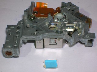
Here is how a DVD drive looks like.

Unscrew the holding screws and remove the panels of the false-housing.


The facial panel is kept by latches. Unlatch them or just break them. Noter that the facial
panel can be removed more easily if the pan is having been moved out.


Below it is shown where is the very optical head of the DVD drive (marked by the red contour).

Unscrew the holding screw of the guiding arms and remove the carriage from them.


Carefully begin to dismantle the optical head of the DVD drive. Remove lids and boards one by one.
Occasionally You will see a number of small lenses and mirrors. The mirrors will have different sizes and colors.


The mirrors are usually glued to the body of the head by some drops of (possibly epoxy) glue.
Using a forceps or narrow pliers one can usually safely remove the mirrors without a damage to the reflecting coating.


Some of the mirrors found inside the head will probably have a yellowish shade and others - reddish.
Usually the yellowish ones are the best for the rhodamine laser .
However this hint is not 100% working. Sometimes the different mirrors visually have the same color and shade.
In other cases the shades are unusual (i.e. greenish mirrors). In rare cases the reddish mirrors appear to be
better than the yellowish ones.
In order to check the usefullness of the mirror let a beam of a red laser pointer to pass through the
sample mirror. Better use the common household pointer (wavelength 640-650 nm) rather than the powerfull one,
having been made of a DVD diode (wavelength 680 nm). The applicable mirror should let some part of the
beam to pass through. The beam spot should dim sufficiently when You put the mirror into the beam.
(~10% of transparency). If the coming through beam does not dim that mirror is useless.
If the beam of the red laser pointer dims too much after having passed the mirror - such a mirror still
can be used but the output energy of the dye lase will be lower. In the first tries however the mirror
with the lower transparency is better than a more transparent ones. Below there is a photo of a try to
show how the correct mirror works. Due to the color and brightness distortion of the camera the photo cannot
serve as the exact ethalon of the transparency, but it still provides the general impression. The laser
pointer shines from the left. So the spot of the reflected beam is to the left from the mirror. The spot
of the passing beam is to the right of the mirror. Compare the brightness of both spots.

THE ALIGNMENT
↑
For the alignment we shall need a red laser pointer. Better the one fed by AA or AAA type batterries.
Keychain type pointers have too little working time - You'll loose Your funds with the replacement batterries.
The first thing, Your need to make, is a screen with a pinhole. The best material to make it is the
aluminium sticky tabe. Its aluminium foil is completely opaque to the light from the opposite side from the screen,
and the white paper side helps to see eventhe most weak reflected spots.
Cut a square 15x5 mm or 20x20 mm from the aluminium sticky tape. At the center of the square
punch a hole with a diameter of ~0.5 mm

Now one needs to attach this screen onto the "face" of the laser pointer. The aluminium side
towards the laser pointer. (The paper side will correspondently be turned outwards.)
During the screen attachement it is needed that the beam of the laser pointer comes through the pinhole evenly.
(The most of the beam will be cut off, but dont worry this is normal. The remaining part of the beam will have
better quality after that.) In order to put the pinhole above the most good and powerfull part of the beam
You should move the screen in the process of the attachement so use an elastic glue (gummy one or a polyurethane one)
or just use a plasticine.

It is better to attach the screen onto the laser pointer having been turned on. Find the position of the screen when
the beam coming through the pinhole becomes most perfect.
Further on the laser pointer equipped with such a screen we'll name as alignment laser.
Turn the alignment laser on. Install it more or less horizontally and fix it (e.g. in vise). I hope there's
no need to mention that the beam of the alignment laser should be directed to a place where You can place the device,
You are going to align, and not towards some dark corner hard to access.

The principle of the alignment is shown on the picture below. The goal is to set both mirrors to be parallel to each other
and in addition to it nothing should break a path for the beam that will be developed between the mirrors.
The mirror can be set to be perpendicular to the alignment beam by watching the spot of the beam, having been
reflected from that mirror. When the reflected beam is coincident with the accending one (when the spot of the
reflected beam hits the pinhole of the screen on the alignment laser) it means that the mirror is set perpendicular
to the alignment beam. When both mirrors are set to be perpendicular to the same alignment beam they obviously
appear to be parallel to each other.

In our case we are aligning the laser cell windows, not the mirrors. (However any windows are mirrors in some sense.
They only have lower reflectance, but it tends to mke things easier.) We need to set our dye laser (the laser being aligned)
and and set it into such a position that the alignment laser beam can freely pass through the tubing of the laser
being aligned without any bouncing and (preferrably) without touching the walls of the tube.
The tube of our laser has small bore (2..2.5 mm) since that the last condition is rather hard to fulfill.
In order for the alignment beam do not thouch the walls the alignment beam should be narrow enough.
It is sorrowfull but due to the natural divergency of the beam of the laser pointer You will not be able to position
the laser being aligned too far from the alignment laser. Use the distance ("alignment arm") from 30 to 50 cm.
It will certainly make the alignment less precise but will still be enough for our purposes.
They usually recommend to align the dry laser ando only after that - to fill it and to realign again.
(Further on it will be evident where this advise roots from.) However the complete drying of the dye laser is long and
complicated process, and the incomplete dryng is not helpfull due to the drops of liquid in the tubing. So I abstain
of giving You such an advice. Lets begin from filling our laser with the liquid (with the dye solution or clear
alcohol. See above how to do it correctly.
After filling the laser, put it into the alignment beam and achieve the undisturbed passage of the alignment beam
through the dye laser cell tubin. I know it is easier to say than to do, but any oral advises will be of not a much help here.
I can say that it is more robust to move the laser being aligned rather than to turn the alignment laser.
Lean and shift the laser being aligned until the alignment beam will pass through it properly.

When the proper pass of the alignment beam through the laser cell tubing was achieved begin to align the front
window. (The window most close to the alignment laser we will call the front window. And correspondently the window most far
from the alignment laser we will call the back window.)
First of all one should find on the screen (on the alignment laser) the spot that relates to the front window.
Simply tilt the plate that carries the front window. That spot, which moves most vividly on the screen, is the one
that relates to the front window.

Sometimes the laser (being aligned) may be bad assembled and the reflected beams are just far away
from the screen. One can try to perform (a shamanic) dance with a piece of paper around the screen in tries to find, where that spot finally is.
One could also try to preliminary set the ending plates to the almost correct position using a
school drawing triangle.
When the spot from the front window was found, one needs to force int into the pinhole in the alignment screen.
One by one tighten the holding-alignment screws (the ones that compress the sealing gasket or the o-ring) and drive
the spot to the target hole. Try not to break the sealing though.
If the plate is already jammed and the spot is yet not in place - it is possibly that the laser is too curved
and needs to be redesigned.
The most important thing in aligning the liquid lasers is that the solution refracts the light.
Since that when the window tilt changes the beam path behind the window does also suffer the changes.
So after any sufficient change of the window tilt You should tune the position of the laser cell
to restore the good passage of the alignment beam through the cell ("to put the cell on the beam" again).
Normally the position of the window does not stay intact in this process. The window should then be aligned again.
And then it again is needed to put the cell on the beam... Essentially the process becomes iterational.
If nothing evil happens, each consequent iteration gives the position of the front window being more and more
close to the perpendicular relatively to the cell tube axis. Three or four iterations and the process converges.
I.e. the reflection of the alignment beam from the front window can be returned into the pinhole in the alignment screen
with having undisturbed passing of the alignment beam through the cell tubing (i.e. without bouncing and unwanted
touchings). When this is done one may proceed to the alignment of the back window.
The alignment of the back window is simplier, because the changes of the passing alignment beam direction does not
affect anything. If the spot from the back window lies in the limits of the screen, then simply regulate th
holding-alignment screws to drive the spot into the pinhole. If the spot from the back window is outside
the screen, most probably the search for it wit a piece of paper around the main beam will be in vain.
This is due to the fact that the reflected beam is limited by the tube. It can be advised to release the holding-alignment
screws of the back plate and to tilt the plate by hands until You see the reflected spot on the screen. Make sure
that the motions of the spot respond correctly to the tilts of the plate (i.e. make sure that the spot is direct, not
bounced or reflected.)
When both spots (one from the front window and one from the back window) hit the pinhole in the alignmet screen precisely,
and if the alignment beam goes through the laser cell without touchings and bouncings the laser may be treated as
being aligned, and You may proceed to mounting the mirrors.
PUTTING THE MIRRORS ON
↑
This laser has comparatively large Fresnel number, but despite of this, due to some not fully understanded reasons
it behaves like a waveguide laser. Particurlarly it is shown as the unusually strong dependency of the output power to
the spacing between the mirrors and the windows. (Or between the mirrors and the ends of the glass tubing.)
E.g. when the mirrors are placed in 15 mm from the windows the output of the laser drops more than 10 times.
The most simple solution of the problem is to put the mirrors directly onto the windows.
No additional mirror mounts are needed. So the window keeping plates serve also as the mirror mounts.
Fortunately they've already been aligned at the previous stage.
To provide the safe life of the dielectric mirror coating when it contacts with the hard glass surface
of the window, we will use thin paper spacers. The good round holes in the paper one can obtain with a help
of an office paper puncher.
Take a sheet of paper and punch a number of holes in it.

Then use a scissors to cut out small papers already having the holes. The area of the paper gaskets should be
slightly larger than the mirrors being used.

Put the paper gasket onto the window, and put the mirror above the gasket. The reflective (coated) side
of the mirror should be turned down (towards the laser cell tubing). Make sure that the mirror sits evenly,
on the gasket and the gasket lies tightly on the window surface. This provides parallelism between the window and the mirror.
And since the windowa are already parallel to each other, the correctly plaed mirrors will also be parallel to each other.


Fix the mirror with some small drops of a hot glue (glue-gun).

Repeat the procedure with the second mirror.
FINAL ASSEMBLAGE
↑
The laser cell is ready, it is flled and aligned/ The capacitors are ready, The spark gap is ready.
It only remains to put all this together and to test the laser just having been created.
FIRST LIGHT
↑
There s nothing special in operating this laser, because the filling and alignment have already been done
at the previous stages. Now it is remains just to connect the laser to a power supply (having enough voltage
to trigger our spark gap) and the laser will start to operate.

The photo above - the laser is working on rhodamine 6G solution. The operational properties on the rhodamine-containing permanent markers (Centropen, CrownHijell)
do not differ principally - those markers contain the same Rhodamine 6G and it is pure enough.
Using the juice from pink fluorescent markers the laser works weaker. The photo below shows the lasing
on an extract of ErichKrausen marker. The extract was obtained through the vinegar milking procedure (see above).

Below is the photo of a version of this laser that gas a piece of a ball-pen rod in place of the glass tubing. (Run on rhodamine 6g). It appeared to be operational (barely lases) but has much less power. Similar to the case when the mirrors are separated from the windows by some distance. One may suppose that the polyethylene ball pen rod does not support the waveguide mode and this diminishes the power.


If the laser fefuses to lase or something bothers You see the troubleshooting below.
TROUBLESHOOTING
↑
the laser does not lase
First of all check (by hearing) the frequency of the spark gap triggering. If it has suddenly
grown up (in comparison with how it was at the first turning the laser on),
it probably gives the evidence that the dielectric body of the spark gap was fried up
and the triggering voltage has become low. (breakdowns slide along the surface)
SOLUTION: open the spark gap and clean it.
If the spark gap triggering voltage is ok, it is possible that the dye solution had aged.
The dye solution once having been put into the laser suffers from aging and loses its
lasing properties. Dependently to the materials used in the construction of the laser the dye solution
lifetime may vary from several hours to several weeks.
SOLUTION: refuel the laser with a fresh dye solution.
Sometimes, essentially when making the solutions from markers, the liquid contains some dust.
This case after having refueled the laser let it to stay for some time. After the dust have settled
the lasing will appear.
If the dye solution is clean fresh and the triggering voltage is proper, the last resort is to
realign the laser. Remove mirrors and the spark gap, and make the alignment procedure from the beginning.
When aligning pay attention to the shape of the alignment beam spots. If the spots are
"cloudy", it is the sign that the windows are dirty. It is fortunate if they are dirty
at the outer side. In this case just clean them. If the windows are dirty at their inner, You will have to remove them, clean them and glue them up again.
Ifthe alignment is correct the laser lases from the first pulse. A bit of misalignment the laser
can self compensate due to the leaning of the beam inside the cell on the thermooptic distortions.
If there is no lasin in the first pulse, let the laser to operate further on. It will possibly lase
after fifth or tenth pulse.
it lases but then dims and quenches.
Without circulation of the liquid the laser is able to repeatedly produce pulses once per three seconds continiously.
If Your repetition rate is higher just make it lower. E.g. connect a ballast resistor rated to several tenth
of megaohms in series with the laser.
If You re insistin on the high repetition rate use a pump an dye circulation mode.
laser's spot is bad
Usually if the laser is aligned correctly the first pulse gives very good, almost perfect, powerfull spot.
Consequent pulses are worse and worse. If You need a good spot - lower the repetition rate and/or
use the dye circulation.
It should be reminded that liquid lasers are generally not distinguished by a good beam quality.
So the reason may be just in the unwarranted expectations.
the laser looses the alignment too fast
The good order laser keeps the alignment in the limits necessary for its operation for several weeks or more.
If In Your laser the smots move to disorder in minutes, check the windows they have probably unglued.
there are flashovers and the lamp does not shine the flasovers from one lead to the foil reflector and further from the foil reflector to the other lead
are the good sign that the lamp is dead. When the lamp is in a good order the breakdown inside it surpresses any outside flashovers.
The outside flashovers mean that the lamp has sucked an air and can not further be used as the lamp.
SOLUTION: replace the lamp
THE COMMENTS
↑
My numerous attempts to make a cheap and small (even if being a low power)
dye laser by different twisted approaches gave fail after the fail. (Some examples of the twisted approaches were
the lamp completely sunk into a cuvette with the dye solution, or a wide angle image transfer from the
lamp surface to the surface of the cuvette.) It appeared that it was needed just to carefully scale the large
dye laser to the small sizes. As soon as it was done it lased without difficulties.
The wide spreadness of the DVD drives solves the problem of laser mirrors affordability.
So despite the laser still has the resonator, it contains no rare or hard-to-get components.
THE POWER
↑
The laser yields several hundreeds of microjoules in the beam. Certainly it is not very much.
However if we take into account that the pulse duration is about 100 ns the output power becomes
equal to several kilowatts.
SCALABILITY
↑
Usually the dye lasers are made in larger scales (by size, by energy and of course by the price).
Due to the fact that this laser was specially designed by scaling down the larger systems
it is senseless to discuss the scalability towards the enlargement.
The main limitation in downscaling is how thin lamp You can obtain and how thin tube You can get.
The simple shortening without decreasement of the diameter will soon meet our inability to lessen the
resonator losses following the lessening gain.
Downscaling with decreasing the diameter meets not only the problem of the resources affordability
(very thin lamps and glass tubings) but also the nanotechnology problems.
E.g. a thermometer capillary has 0.3 mm bore. And how to align that laser?
It needs the completelt different schematics of the resonator and completely different materiald
(in the first order it needs the solvents having thr refractance higher than the refractance of the glass)
And if You also want such a thin laser to have a good efficiency You will need to choose a lamp having the bore
of the same order that Your capillary has. In the reality such lamps do exist (ISP-15 for example) but just
imagine the problem of aiming the image of the lamp to fit the capillary when all things are inside an elliptical reflector.
The said above leads to thoughts that the theoretic possibility to the further scaling down of this laser
meets high difficulties in practice.
However the optimisation of the design gives goot possibilities to make the laser even smaller
without changing the sizes of the lamp, glass tubing and the resonator.
APPLICATIONS
↑
The first thing that comes in mind is the use ath the laser pointer. The yellow beam laser
pointers are very exclusive and very expensive. On the other hand the rhodamine 6G laser as we can see
is small (and can be made even smaller) and when being used with a (batterry powered) portable power supply
the whole laser can easily be made portable. As the portable HV power supply one can use a common stun gun (electric shocjer).

If You are pursuing the even smaller design You can construct You very own power supply. The task is rathe easy
sinse the needed 10 kV are in lower range of the high voltage, and is comparatively easy to work with.
Other applications - signalisation, communications, ultrafast photo. With some modifications of the resonator
most probably that the laser will be usefull for some special kinds of the holography (however this fact is yet to check out).
OPERATION SPEED OF THE PUMP CIRCUIT
↑
The upper laser level lifetime in the dyes is small. Different estimations give from 2 to 4 ns
for the Rhodamine 6G. Thus in case the flashlamp pumping the gain and the stored energy are defined not
by the energy of the pump source but rather than that by only its power. It is easy to understand that
when the stored energy is limited the faster it will be turned into light (i.e. the shorter pulse) the better.
The second unpleasant property of the dyes is that they have parasitic (not tasking part in lasing process)
energy levels and those levels have very long lifetimes. Those levels are called triplet ones (note
that the laser active levels are the singlet ones). the lifetime of the triplet levels in the dyes can be up to several
hundreeds of microseconds. I.e. even if the probability of the dye molecule to get to the triplet level
is much less than the probability to get to the laser levels, due to the fact that the triplet lifetime is many
orders of magnitude longer, the process ends with most of the dye molecules gone to the triplet state.
Worse of all that those moleculas not only are unable to participate in lasing (at least till the next pulse),
but they have considerable absorbtion of the lasing light, i.e. they increase losses in the resonator
and finally quench the oscillations.
In the history of the dye lasers there was a period when the accumulatiaon of the moleculas in the triplet state
was considered as the main reason preventing the dye laser from the ability of the continious operation.
Further on, however, it was shown [1] that in the most good laser dyes (like rhodamine and
fluorescein) the triplet lifetime can be seriously reduced by the special additives
triplet quenchers. WHen the triplet lifetime is reduced the dye lasers appear to be able
to the continious operation with laser pumping and with flashlamp pumping the output pulse duration can
reach several hundreeds of microseconds. In the last case the lasing stops mostly due to the resonator misalignment
on the thermooptical distortions rather than due to the triplets accumulation.
As those "magic" additions that quench the triplet states the next species are commonly used:
the cylcooctatetraen (hard to spell out and even harder to obtain) and the oxygen of the dissolved air.
The latter is much simplier for the DIYer. So there's no need to avoid the dissolved air. On the contrary
it helps lasing greatly.
Lets however imagine that the triplets are still interferring. For example one has failed in getting
a cyclooctatetraen and there is no air in the solution (good example: solid state dye lasers). Or either
the laser utilizes such dyes that have no known triplet quenchers (good example: the coumarines).
So from the beginning of the pumping pulse the accumulation of the triplets starts. It goes slowly
(because the triplet yield is small for good laser dyes) but unavoidably (because the moleculas having been
got into the triplet state have no chance to leave from there at least till the next pulse).
This unavoidable accumulation of the triplets increases the resonator losses and hereby the laser threshold.
As it was said above the gain in the laser depends only to the pump power being absorbed in the dye.
It is understandable that if the peak of the power comes too late (when too much triplets have been accumulated)
the laser threshold may even become unreachable even at the peak of power. If we additionally take into account
that the rate of triplet accumulation is proportional to the pumping power (similarly to the singlets accumulation rate)
teh we'll get that the impoertant thing is not the absolute time between the start of pulse and the peak of power, but
the relative time. I.e. the shorter the pulse is the shorter time should be between its start and the peak. I.e. the shape of the pulse
is important. In order for the laser to have a chance to emit light in maximal extent before the triplets have accumulated,
the pumping pulse should have a sharp front, it means that the peak power should go as
soon after the pulse beginning as possible.
Thus when the triplets do not interfere seriously the pumping pule for the dye laser
must be as powerfull as possible, and when the energy is fixed, it is equivalent to
"as short as possible". And when the triplets are interferring the pulse must be not only
as short as possible but also it should have the lowest possible risetime.
It should be stressed that the said above relates to the pulse of light being emitted by the flashlamp,
and the shape of the light pulse generally has rather far relation to the shape of electric current pulse
feeding that flashlamp.
The light pulse consists of two parts (Fig 6.). The front rising part (zone I on Fig 6.)
and the back descending part (zone II on fig 6.). The shape and duration of the rising part
is determined only by the balance between the heat coming with the electric current and
and the heat being lost due do the different leaks. I.e one can say that the shape of rising part
is generally determined by the shape of electic current pulse but distorted by other processes.
The shape of the back descending part is determined only by the law of the lamp cooling.
Its duration is the most simple to estimate.

Figure 6. The shape of the light pulse having place when feeding a flashlamp from a low inductance capacitor.
The temperature falling time can be estimated as tauT=Ql/Wl, where Ql - is the amount of heat stored in the lamp plasma,
Wl - power of the heat losses.
WARNING! the scientists do their calculations with a precision up to 0.1%. We are
DIYers so all the estimations we will make with a precision to the order of magnitude.
For us there's no need to be so self fascinated to aspire the power of the calculations. We only
need to see what depends to what, and what to change to improve the laser. For these purposes our rude estimations will serve well.
The heat stored in lamp Ql we will determine using the old good school formula of the ideal gas
internal energy: Q=mu*(X/2)RT, where T is the absolute temperature, R=8.3 J/(mol oK) - the universal gas constant;
mu - is the amount of the heated substance in the lamp (measured in moles),
X - the number of degrees of freedom.
Since the xenon being used in lamps is the monoatomic gas the X should be equal to three.
But in the reality in the high temperature plasma many energy levels are excited (or else it wouldn't emit light)
so X is not known precisely. However as You will be able to see later on the final result depends to X much less
than to the other parameters.
The amount of substance between the electrodes of the cool flashlamp one can determine as
mu=(P/P0)(V/V0) where P - the pressure in the (cool) lamp, V - the gas volume between the electrodes,
P0 = 1 ata = 760 torr = 14.7 psi = 101 kPa - the normal pressure
V0 = 22.4 liters = 22 400 ml = 2.24e7 cubic mm - the volume being occupied by a mole of gas at normal conditions.
To determine the heat losses lets assume that the lasma loses heat only due to radiation.
And that the plasma can be treated as a black body: Wl=sigma*S*T^4,
where S - is the area of plasma surface,
sigma = 0.57e-11 J/(sec sq.cm. oK^4) = 5.7e-14 W/(sq.mm. oK^4) - the Stephany Boltsman constant
And finally
tauT=Ql/Wl= mu *(X/2)RT / (sigma*S*T^4) = (P/P0)*(V/V0)*(X/2)*R / (sigma*S*T^3) = P/(P0*V0)*(V/S)*(X*R/2) / (sigma*T^3)
We already can see that the time constant of the temperature drop is reversely proportional
to the cubic power of the plasma temperature and linearly proportional to the (V/S) ratio i.e.
linearly proportional to the lamp bore diameter d.
(actually V/S = pi*(d^2/4)*l/(pi*d*l)=d/4 , pi=3.14 is the "pi" number, l - is the lamp length,
and we've neglected the area of the ends when calculating the emitting surface of the plasma)
It can also be seen that the time constant rises with the increasement of the initial pressure in the lamp
I.e. we may conclude that the dye lasers prefer thin lamps with low initial pressure.
If You wish we can estimate the time constant for our lamp. The interelectrode spacing is 25 mm,
the bore is 3 mm, that gives V=176 cubic mm and S=235 square mm.
Glass photo lamps are usually filled wth xenon at a comparatively low pressure [2], so it is reasonably to estimate P=0.05 ata.
Here we get the amount of xenon in the lamp: mu ~ 3.9e-7 mol.
tauT= mu *(X/2)RT / (sigma*S*T^4) = 1.2e5[sec*oK^3] X/T^3
For example with X=3 and T=10000 oK we'll get tauT = 364ns. However this value is of low use for us.
Because this is the temperature time constant and we are more interested in the time constant
of the emitted light..
In order to find the light time constant tauL we will again exploit the same approach tht we've already
used for the tauT: we'll estimate the time constant as the ratio of the peak emitted light power to the
speed of the emitted light power changes:
                        S*sigma*T^4          T^4           T^4       1   T
   tauL=Wl/(dWl/dt) = ----------------- =  --------- = ----------- = - -----
                      d(S*sigma*T^4)/dt    d(T^4)/dt    4T^3*dT/dt   4 dT/dt
Do note that in our previous estimations the ratio of temperature to the rate of temperatur changes was assumed as tauT.
and that leads to: tauL = tauT/4, it can be formulated like that:
the time constant of the emitted light power decreasement is four times lower than the time constant of the plasma temperature decreasement:
tauL= mu *(X/8)RT / (sigma*S*T^4)
Particurlarly for the lamp of ours, tauL=3e4[sec*oK^3] X/T^3, that for X=3 and T=10000oK gives 91 ns.
Additionally the formula shows that dependently to barely known factors X and P
the time constant of the emmitted light decreasement changes only linearly, when dependently to the
temperature (i.e. dependently to the energy input to the plasma) there is the reversed proportion
of the third power (!)
One can say that there is no need to make the electric pulse faster than the 90 ns obtained above.
Others can say that there is no limit to increase the speed of the lamp (to reduce the tauL) just by rising the energy deposition.
However the 10000oK taken in our estimations is very adequate as the estimation of the top achievable or the top allowed temperature.
To ensure this lets remember the Wien law: that the spectral position of the energetic luminous exitance peak obeys
the formula: lambda_max=b/T, where b = 2.8e6 nm*oK - is the Wien constant. Substitute here T=10000oK and get
lambda_max=289 nm. It means that at ten thousand of kelvins even the maximum of luminosity has hit the blue border
of the glass transmission. Surely the further increasement of the temperature will only lead to the rapid decreasement
of the laser efficiency. (However one may expect that the energy threshold will continue to decrease because
the part of the radiation transmitted by the glass will decrease slawer than the light emittance power rises.)
For (fused) silica the short wave border of the transmittance corresponds to higher temperature of the plasma
(~13000 oK), that gives higer laser efficiency, higer power, lower energy threshold and...
...and faster rate of the photochemical dye degradation. For the lasers with cell tubing and the lamp made of silica
one can easily observe the dye degradation in real time scale.
Another reason of getting 10 000 oK as the top limit is that it is very hard to heat the plasma to above this temperature.
Especially if one needs to do it fast, during those tenth of nanoseconds that are needed for the dye laser.
The reason is that the conductivity of the plasma rapidly increases with the rise of the temperature.
In [2] there is a formula for the cunductivity of the plasma:
(1/ro)[sm/cm]=1.55e-4*T^(3/2)/(Z^2*ln(A))
Lets take the average charge of the ions to be equal to unity: Z=1 and the Coulomb logarithm equal to three
( ln(A)=3, as it was recommended in [2] ) we will get:
(1/ro) = 0.52-4*T^(3/2)[sm/cm]
For the temperature 1e4oK the conductivity will be: 1/ro=52[sm/cm], and correspondently the specific
resistance ro=0.019 [Ohm/cm]. The exact sizes of the lamp in our laser (d=0.3 cm, l=2.5 cm) will give the lamp resistance equal to Rl=0.67 Ohm.
The electrotechnique course teachs us that the energy from a generator can be effectively absorbed by the load
only when the impedance of the generator is lower than the load resistance.
In our case the load is the flashlamp and the generator has the form of circuit
consisting of the storage capacitor and the stray inductance (of the capacitor itself,
of the connecting shims and of the spark gap). If neglecting the ohmic losses the impedance of such a generator is
sqrt(L/Cs), where Cs - is the storage capacity, L - is the total stray inductance. Hence for the effective
energy input to the lamp the next condition should be fullfilled:
sqrt(L/Cs)<Rl => L/Cs < Rl^2 => L < Rl^2 * Cs = 0.45 Cs.
I.e. each nanofarad of the storage capacity lets us to have only 0.45 nanohenry of the stray inductance.
It is very hard to obey this condition in practice. And even harder whwn the plasma temperature is higher
(Rl becomes lower). The allowed stray inductance decreases being reversely proportional to the cubic power of the
temperature.
In the reality it looks like "superconductivity" of the plasma. When rising the charging voltage
on the storage capacitor we reach the point when the current begins to
"fall through the lamp" and instead of the fast heating we observe the slow heat deposition
by the weakly dumped oscillations of the RLC tank circuit. In comparison to the decay constant of the
oscillations the rate of the heat losses can not be treated as neglectable and the rise of temperature
becomes slow or even stops.
We can see here that our natural tendency to reduce the pump pulse duration
my means of the usage the lowest possible Cs and the highest possible charging voltage Uo is doomed...
(or at least inefficient). An explanation of this tendency You can find in [3] where
it was noted that if the stored energy is equal to Cs*U0^2/2, one can keep it constant
when decreasing C0 by means of rising the charging voltage U0. The characteristic time of the discharge
(equal to pi*sqrt(L*Cs) for oscillation discharge mode and Rl*Cs for the aperiodic one)
should then be reduced. But in the reality this reduction gives nothing
because it goes to the mode of the low damped oscillations, where each period of the sine wave gives only a
small part of the energy into the usefull heating of the lamp.
Lets return to the figure 6. After the said above it is clear that in the modes with good energy deposition effectiveness
(when L< Rl^2*Cs or L~ Rl^2*Cs) the duration of the rising part of the pulse
(zone I on fig. 6.) is completely determined by the discharge time of the storage capacitor through the lamp
In practice it is equal to one or two half periods of the strongly damped discharge current oscillations.
In the modes of low efficient energy deposition
(when L>> Rl^2*Cs) the duration of the rising part of the pulse is determined by the decay time
of the oscillations in the RLC tank circuit and the tail of the decayed oscillations can even disturb
the decreasing part of the lamp pulse (zone II on fig.6.).
If we assume that there's no sense to make the discharge time constant to be much lower than the
lamp cooling time (being, as we determined earlier, equal to ~100ns for the 10000oK of temperature)
we will come to condition: pi*sqrt(L*Cs)=100 ns or Ls[H]*Cs[F]=1013e-18 or Ls[nH]*Cs[nF]=1000.
If then we take the stray inductance of the spark gap to be 20 nH, the inductance of the connections to be ~20 nH
and the stray inductance of the capacitor to be ~20 nH, then the total stray inductance L=60nH will define us the
possible capcity of the storage: 16 nF. The pulse forming network impedance will then be
sqrt(L/Cs)=1.9 equivalent Ohms. This value is greater than the load (0.67 Ohm by our estimations) but still not by the order of magnitude.
so we can say that our laser operates near the mode of the effective energy deposition.
Actually if we remember that the resistance of the spark gap is nearly 1 Ohm in the triggered state, and if we add this
value to the lamp's resistance, it will appear that our laser's circuitry mode of operation is even more close to the critical
one than it seemed above.
Here are two oscilloscope traces of two different lamp flashes


The flashlamp risetime is about 50 ns and the fallout time is about 150 ns. Note that the
deviation from the theoretical value, we got above, s less than 2 times. Not bad for such
a simple theory, heh?
The next two pictures are the oscilloscope traces of two different laser output pulses


You can see that the laser output duration is slightly less than 100 nsec. Do also note that
the amplitudes of all traces are not intended to compare. For each trace I varied the
positions of the photodiode sensor and diffusers specially for not to overstress the sensor.
It means the amplitude visible on the traces represents not the real strength of the light,
but only my skills to drive it into reasonable range.
The next picture shows a trace of a pulse from an air-pressure TEA nitrogen laser. It is
here to give You some sense of how fast my combination of the oscilloscope+sensor is.

Since the real pulse duration is well below 1 ns, it means that all the measured 10.5 ns
represent the time constant of my measurement system.
THE LASER CELL DIAMETER
↑
When discussing the influence of the cell diameter onto the laser's operation it has sense
to consider two different cases:
- the case of the constant energy stored in the laser medium upper level
- the case of the constant illumination (i.e. the constand power density
of the light that hits the walls of the cell tubing)
There exist a very mechanism to describe the gain in lasers. And this mechanism is named the "cross section of the stimulated emission". They usially designate it as "sigma", but sigma
is already occupied here as the Boltsmann constant. Lets then call it sigmaE (emission).
Without getting into excessive details we can simply write down: Ku=exp(sigmaE*n*Ll), where
Ku is the full gain per pass through the laser medium, sigmaE (as we stated above) is the
stimulated emission cross section, n - is the (volumetic) density of the active centers
(of the excited moleculas) and Ll is the length of the active medium in the direction of the
pass being discussed.
For our purposes we won't need to know the value of the stimulation cross
section and indeed You rarely know it beforehand. Luckily enough I've found it
for the rhodamine 6G see curve designated as sigmaE on figure 7 (cited from [4])

Figure 7. Cross sections of RHodamine 6G.
SigmaE - stimulated emission cross section
SigmaA - absorption cross section
SigmaT - cross section of triplet forming process.
Lets return to the Ku=exp(sigmaE*n*Ll) expression. and lets multiply and divide the
expression in the brackets under the exponent by hv - by the energy of the quanta:
Ku=exp(sigmaE*n*hv*Ll/hv)
Lets also multiply and divide the expression under the brackets by pi*d^2/4 (remember
that d is the cell tube bore diameter):
Ku=exp(sigmaE*n*hv*Ll*[pi*d^2/4]/hv/[pi*d^2/4])
Now do note that the Ll*[pi*d^2/4] is the volume of the laser (or the active volume
of the laser if You wish). So the n*hv*Ll*[pi*d^2/4] just gives the energy in the laser.
To be more precise if we say tht hv is the enegy of the laser quanta this will give us
the (stored in laser medium) energy, that can be extracted as the laser radiation. If
we say that hv is the (average) energy of the pumping quanta the expression will give us
the pumping energy having been absorbed in the active medium. So there is some
flexibility, and since that flexibility is rather handy lets assume that the value of E=n*hv*Ll*[pi*d^2/4] is just the energy in the active medium of the laser. If needed
we will refine the specification further on. So:
Ku=exp(sigmaE*E/hv/[pi*d^2/4]) or Ku=exp([sigmaE/hv]*E/Sl)
where Sl=pi*d^2/4 - the area of the cross section of the laser cell tube (bore).
Since sigmaE and hv are the parameters, characterizing the laser medium, they may be treated
as constants. And if we assume that the absorbed (or stored) energy E is fixed, we
well immediately get that the gain in the laser depends only to the cell diameter (or to the
area of the cell cross section). The larger the diameter - the lower the gain.
Lets consider the relation of gains in two lasers having the same energy stored in their
active volume, but having different diameters d2 and d1. Let Ku(d2) be the gain for the
laser having diameter d2. And Ku(d1) be the gain for the laser having d1.
Ku(d2) = exp(sigmaE*E/hv/[pi*d2^2/4]) = exp(sigmaE*E/hv/[pi*(d1*d2/d1)^2/4]) =
= exp([d1/d2]^2*sigmaE*E/hv/[pi*d1^2/4]) = exp( [d1/d2]^2*ln(Ku(d1)) )
And finally Ku(d2) = Ku(d1)^([d1/d2]^2) (*)
Consider an example. Say some laser has a gain equal to 20% per pass or, in terms of
absolute values: Ku=1.2. And say the laser rod diameter is 6 mm. We want to know how will
the gain be changed if we reduce the diameter to 2 mm and keep the energy in the laser
medium at the same level.
SOLUTION: Ku(d2) = Ku(d1)^([d1/d2]^2) = Ku(d1)^9 = 5.16
So the reduction of the diameter by 3 times caused the rise of the gain from 20% per pass
to full 416% per pass (!).
Do note that we did not actually need to know neither the exact value of sigmaE nor the
length of the laser. We even did not need the exact values of d1 and d2, only the ratio of them.
Do also note that in case we had initially the gain of 10 times per pass, we would end up
with the 1e9 times per pass just by decreasing the diameter 3 times. So a normal laser could
end up being well superradiant.
Well then, it is understandable that it is hard to decrease the diameter of the laser rod
or cell simultaneously with keeping the absorbed energy at the same level.
In trying to get the expression (*) if we kept an eye to the possibility for energy E
to be variable, we might get:
Ku(d2) = Ku(d1)^((E2/E1)*[d1/d2]^2) (**)
Where E1 is the energy (stored) in laser having d1 diameter and E2 is the energy (stored)
in the laser having diameter d2.
How to estimate the ratio of energies E2/E1 ?
Lets assume that both lasers are pumped by the same lamp (fed by the same pulse forming
network). In this case we may propose the case of constant illumination. It means that
each part of the laser cell surface is affected by the same density of the incident light,
regardless te first laser it is or the second. (We'll not bother to take into account the
fact that the far from lamp side of the cell takes less light than the one facing to the
lamp. We'll also neglect the distribution of light along the cell's length. All those
corrections will affect only the quantity but not the quality of the result.)
Now we can assume that the pumping energy having entered into the cell is proportional
to the surface of the cell. E~pi*d*Ll. And if we decide that all the entered energy is
eaten inside the cells, we can say that: E2/E1 = pi*d2*Ll2/pi*d1*Ll1 = d2*Ll2/d1*Ll1.
One might cancel the length of the lamp in the nominator and denominator, but lets keep it.
It may be usefull in case the lamps in both lasers arent exactly the same but just provide
illumination with the same properties.
Using the expression (**) and thejust obtained E2/E1 ratio estimation we get:
Ku(d2) = Ku(d1)^([Ll2/Ll1]*[d1/d2]) (***)
It means the gain is still increasing with decreasement of the cell diameter!
Not as fast as in the previous case but still does.
A small remark: in order to keep the cell with smaller and smaller diameter to be able
to absorb all the incident light one, of course, has to increase the dye concentration
correspondently.
Another remark: we could generalize the obtained conclusion: we could say that in the
reality there's no actual need to decrease the diameter. We could just continue to
increase the dye concentration and treat the absorbing layer of txe dye as an annular
cell having much smaller cross-sectional area. And using the cross sectional areas rather
than the diameters we couls estimate the gain even it this case, but this way of
thinking may lead this humble guide top grow into a laser-physics treatise.
The last case to discuss here is the case of low absorbtion - when the absorbed
energy is so small that it can be treated as being proportional to the cell volume
(and surely to the illumination density, but this is aside of the consideration).
In this case E2/E1 = (Ll2/Ll1)*(d2/d1)^2 and in the expression (**) the ratios
of diameters can be canceled.
So Ku(d2) = Ku(d1)^(Ll2/Ll1)
In real lasers You tend to get a decent efficiency and this prevent You from keeping
the absorption small enough. So the last case is not in close relation to the real
devices. It is here rather to show where the status quo is restored: the gain becomes independent to the cell diameter when the absorption of the pump light in the active medium is very small. In all other cases, as we've seen above, the gain
increases more or less strongly with the reduction of the cell diameter.
[1] F.P. SCHAFER, Dye Lasers. in Topics in Applied Physics, vol 1. Springer-Verlag, Berlin, Hoidelberg, New York , 1976
[2] I.S. Marshak. Pulsed Light Sources. M.: Energiya, 1978.
[3] Jon Singer, TJJIIRRS-15A Towards affordable dye laser...
[4] W.Brunner, K. Junge. Wissensspeicher Lasertechnik. VEB Fachbuchverlag, Leipzig, 1987
<< HOME PAGE |


