As it comes, my hands have reached the metal halides lasers. (Special thanks
to Andrew Frankenstein, who succeeded to arise my interest to this cumbersome
thing.) Here is the place to tell the results.
Copper Vapour Laser (CVL) is relatively rare thing among the DIY designs.
In addition to the variant, described at pulslasers.de, I succeeded to find
only one alive link from the Sam's Laser FAQ (others, given there are dead).
Plus I've seen a few unfinished projects over the net, however they didnt make
their way to the first light.
Many papers may be written on the properties of the copper laser, that make
it so "unpopular". But there are IMHO two main reasons: too high temperatures
for the laser on the pure copper (that makes one to use rare and expensive
materials) and too complicated high voltage double pulse forming network,
needed for lasers on copper salts. The last one becomes obsolete if one uses
repetition rates in several kiloherts range, but in its own order it requires
several kilowatts of input, and such powerful power supply isnt readily
available for everyone.
Usage of the rotary spark gaps or either digital delay circuits for the
ignition pulses of the thyratrons, or even usage the thyratrons themselves has
always ssemed to be a bit excessive. There are thousands of ways to produce
a pair of high voltage pulses, separated by a certain delay. Of course You may
design Your very own and unique scheme too. The sample, I use, is not better
or worse than one of Yours. It just utilizes the uncontrolles (self triggering)
spark gaps and it is free of low voltage semiconductor devices, that are too
sensitive to high voltage interferences and leaks, and die too often. However
I was to prove the operatonability of such a simple circuit.
Interlude 1. COPPER MONOCHLORIDE
The copper halides lasers usually use salts of single valent copper. These
ones are not hygroscopic and evaporate easily without decomposition. The best
choice among the cuprous halides is CuI/ It has no tendency for oxidation
when exposed to air, and it is easy to obtain: just pour a vial of medical
iodine tincture onto a copper wire. But... Its laser working temperature is
over 600oC. It means You can not use the common glass for Your laser tube -
the softening point of the glass is unsafely close to the temperature of the
operation. Thereby You will have to learn how to get a cuprous chloride. It
works at lower temperatures.
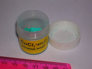
If one has access to dichloric copper salt, the simpliest way to obtain
monochloric one is to boil the copper chloride with glycerol.
The procedure:
WARNING! ALL SALTS OF COPPER ARE TOXIC!
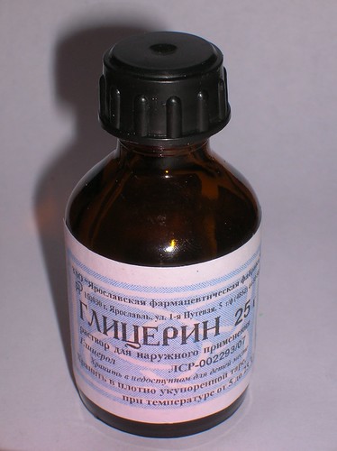
The common "school type" test vial was filled with 6 ml of glycerol. (No
need to search for anhydrous "dynamite" glycerol. The common one, widely
used for skin softening, works well.)
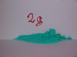
2 grams of dichloric copper tetrahydrate (CuCl2*4H2O) was added into the
test vial.
It is better to add the salt to glycerol, otherwise You can find
problems with wetting the bottom of the test vial.
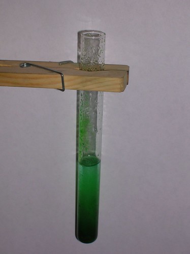
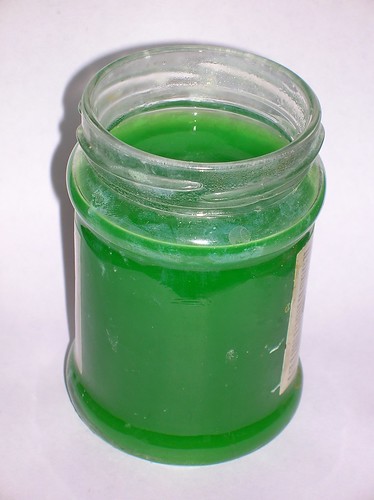
The test vial with the mixture was heated gently over 15 minutes on an
alcohol lamp flame, keeping the soft boiling of the liquid. During the process
all solids become dissolved, and the solution begins to change color towards
the dirty grey.
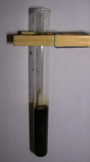
There may appear an unpleasant odor. There are 3 signs of the end of the reaction:
- Any traces of green color of the solution vanish. The liquid in the test vial becomes dark brownish grey.
- The solution begins to smell badly.
- The boiling of the liquid becomes bumpy. It becomes hard to keep the
smooth boiling.
After the reaction had finished the test vial was set aside to cool down
freely to the room temperature. Dont force the cooling and dont try to
pour the hot liquid into the cool water! If done so the cuprous chloride
settles in nanocrystalline form, hard to be filtered, and it leads to
the high losses during washing the product.
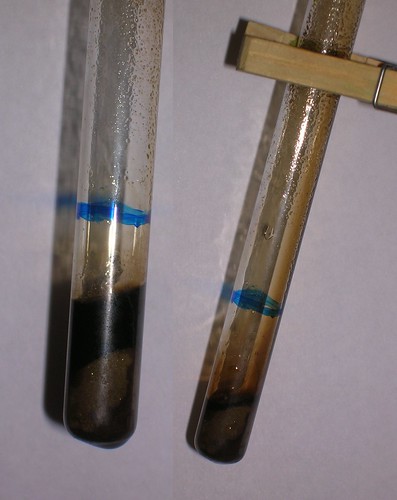
During the cooling the cuprous salts become insoluble in the unknown liquid
that previously was glycerol. They settle on the bottom of the vial forming
nice crystals having comparatively large size. The liquid also contains some
cuprous chloride but not more than 20% of the yield.
Pour the contents of the vial into a cup with cold water and stir until
all the dark viscous liquid is dissolved. If there is enough water, You can
see that the dark color has gone and You have a bluish water layer with
a snow white powder on the bottom of the cup. This snow white powder is
the cuprous monochloride, Wash it 3 times with enough water and 3 times with
small amount of ethanol (or methanol or some other easy drying liquid soluble
in water and unable to solve the product). Dry the powder as quickly as
possible. Yield is about 1 gramm - just enough to load once the laser tube.
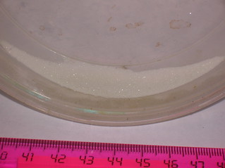
The copper monochloride looks like snow white powder very hard to dry.
When drying it tends to become blue (if it was wet) or grey (if organic
solvents were used). Tiny amounts of the powder are able to colorify the
colorless flame of the alcohol lamp into intense bluish-green color.
Sinse the product tends to decompose it is better to produce it just
before the laser tube loading.
NOTE of 02.02.2016: If Your crystals do not want to precipitate, it means You've added too much of the glycerol. Try to avoid the excess of the glycerol.
1. DOUBLE PULSE FORMING NETWORK
           Cp1
          470 pf

      +-----||-------+
      |              |
  (-) |              |
   0--+-----I (------+-----------------------------+-------------+
      |              |                             |             |
      |     SG1      |                             |             |
      |     10 mm    /                             /             /
      |              \ Rb1                   Rb2   \             \ Rs2
      |              / 91 kOhm             91 kOhm /             / 8.3 MOhm
      |              \                             \             \
      |              /                             /             /
      |              | Cs1    Rdump         Cs2    |             |
      |              | 4 nf   100 Ohm       4nf    |             |
      |              |  ||                     ||  |             |
      |         +----+--||---/\/\/----+----+---||--+----+        |
      |         |    |  ||            |    |   ||  |    |        |
      |     SG2 |    |                _    |       |    | SG3    |
      |    4 mm |    |               /o\   / Rs    |    | 5 mm   |
      |         U   ---          LT1 | |   \ 5k6  ---   U        |
     ---            ---              |x|   /      ---            |
     ---        -    | Cp2           | |   \   Cp3 |    -        |
      | Cs0     |    | 470 pf        \o/   /   470 |    |        |
      | 30 nf   |    |                -    |    pf |    |        |
      |         |    |                |    |       |    |        |
   0--+---------+----+----------------+----+-------+----+--------+
  (+)
Fig 1. The pulse forming circuit. The primary storage Cs0 is Maxwell 37667
30 nf 35 kV type. The secondary storage banks Cs1 and Cs2 are Murata(tm)
high voltage low inductance doorknob capacitors. Peakers Cp1...Cp3 are
K15-4 high voltage low inductance doorknob capacitors. All resistors are
of high voltage types, able to endure 30 kV at least. LT1 - laser tube.
Spark gaps are ball-to-planar type formed by a cup of M12 acorn nut and
the surface of aluminum angle stock. Since the direction of these spark
gaps stressing affects the triggering voltage, the figure shows exactly where
the spark gaps have their planar side and where they have their rounded side.
The schematics of the laser feeding circuit is shown on Fig 1. The principle
is simple and does not need any commentaries. The primary storage bank is made
of Maxwell capacitor due to the only one reason - I just have it and it suits
well. No reason on the Earth requires it (the primary storage) to be of the
low impedance type. Use just any capacitor or bank that has enough capacity and
operating voltage. The same can be said about the secondary storage Cs1 that
forms the dissociation pulse. It also can be of any type. On the contrary the
storage bank in the pumping shoulder (Cs2) must be low ESL and low ESR. Most
doorknobs will suit. Most types of rolled film capacitors won't suit.
Note on the spacings in the spark gap. The spacing in the left spark gap
(SG2) must be smaller than the spacing in the right one (SG3) since the
dissociation pulse must preceed the pumping one. The relation between these
spacings determines the delay between pulses and may vary to a certain extent.
The spacing in the leading spark gap SG1 must obviously be greater than any
of the spacings in SG2 and SG3 spark gaps. Calculations show that the circuit
should be operational when the spacing in SG1 is at least 30% greater than the
spacing in SG3. However the experiment shows that the circuit has decent
reserve of stability only when the spacing in SG1 is twice as large as one
in SG3. When the spacings are set as shown on the figure 1, the pulse forming
circuit produces two high voltage pulses separated by ~200 mcsec one from
another with a probability more than 70%. Another 20% goes to different
delays between pulses (due to the instabilities in the spark gaps) and
the rest less than 10% is the probability of the case when one of the
spark gaps fails to trigger (usually SG3 but not necessary).


Figure 2. The oscilloscope trace of the double feeding current pulse.
The trace was taken on the real gas-discharge tube.
Figure 2 shows the oscilloscope trace of the pair of feeding pulses.
It is the current through the real gas-discharge tube having silica walls,
6 mm bore, and filled with cuprous iodide with nitrogen as buffer gas.
Due to the reasons independent from the pulse forming network the tube
refused to lase. The long falling tail on the oscillogram is the artifact
of the special measurement circuit that provides decoupling between high
voltage powerful circuits and signal measurement ones. Without this
thing the oscilloscope would be irreversibly dead in microseconds. Due
to the same reason the traces were taken by the old and semi-dead PSCU1000
and not by something better. Sorry for that. If You ignore that "slope ground",
You can clearly see two consequent pulses generated by the circuit having
been presented above.
It is good to make some looking windows in the bodies of SG2 and SG3
spark gaps. The flashes visible through the windows can tell You whether
the spark gap has triggered or not. By the correlation between the presense
of the peak on the oscillogram and the fact of spark gap triggering it was
found that the first peak means triggering of SG2 and the second peak means
triggering of SG3, i.e. the circuit operates just like it should do.
The schematics on the figure 1 looks simple and it would be true if the
voltage was low. However the high voltage pulsed circuits are assembled
not by soldering iron and PCB. The very instruments are hacksaw, filer
and drill, and the very material is aluminum extrusion. The final design
of the circuit is shown on figure 3.
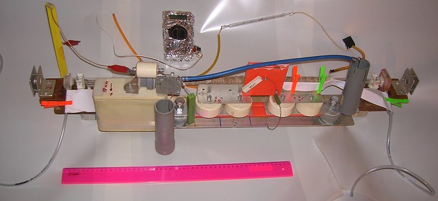
Figure 3. The design of the double pulse forming circuit on the frame
of the copper halides laser.
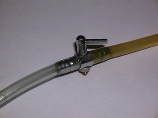
2. LASER TUBE
Laser tube was chosen of the most simple design in the world. A tube
of luminescent lamp was taken, having outer diameter 16 mm and 14 mm bore.
It was cut off to have the length of 720 mm. Its ends are sealed with
plexiglass parts carrying gas hoses and output windows. The plexiglass
parts, the hoses and windows are all sealed by hot glue (glue-gun,
low-molecular polyethylene). The windows are made of pieces of some
microscope sliders. No efforts was paid to adjust or align them in any
way. Actually the back window has a skew of ~5 degrees and the front
one has a skew of ~10 degrees. In addition both skews are directed to
different (random) sides.
The metal hoses are used as the electrical terminals. This solutions
has it own drawbacks, but makes things simplier for the first tests.
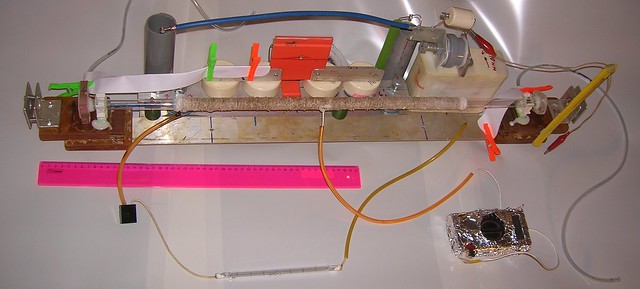

Figure 4. The sizes of the laser tube.
Coil was taken from some 600 W (nominal) electric heater. Its wire was
straightened and wound onto the central part of the tube (see Fig 4).
A thermocouple from a chinese multimeter was attached to the wall of the
tube and then all area to be heated was covered by winding with asbestos cord.
The length of the heated area appeared to be 450 mm, which leaves about 15 cm
between the hot zone and the things loving to be at room temperature (the
endpieces, hoses and windows).
During the experiments with the laser I did not took a risk to plug the
coil directly into the mains. A halogen lamp rated to 1 kW was used as a
ballast resistor. Its warm light You will see in the video in the RESULTS
part of this report.
Experimentally (by heating another lamp glass tube to bending) the upper
limit of temperature was determined to be 400oC. When the central part of
the tube is heated to this temperature the endpieces stay not hotter than
warm by touch (carefully discharge everything before touching something).
The tube was assembled and tested for vacuum tightness. The leak was less
than 10 torr per 24 hours. Or either my valves were responsible for that.
Then the endpieces were removed and the tube was loaded with 1 gramm of
cuprous chloride. In form of three small piles. One pile in the middle of
the heated area and two other piles near the ends of the heated area. When
loading it helps to fill some thin plastic pipe with the powder, to protrude
this towards the unloading point, and to unload the plastic pipe using some
wire or stick as a piston. Take care for not to block the aperture by those
piles.
Generally at this point You may feel sorry that Your tube was not equipped
with a tiller to place the load. For the similar reason don't use too narrow
laser tubes - they will be hard to load and there will be the risk of beam
path blocking (it was the main reason why the 6 mm bore silica tube, that
I've mentioned above, appeared to be unable to lase.)
3. RESONATOR
The resonator was formed by a concave aliminum first surface mirror (just
a piece of a car rearview mirror washed out from paint, taken from my CO2
laser project) and a planar He-Ne mirror. I checked the latter with a green
laser pointer and found out that HeNe mirror has ~50% transmittance for
the green. It is well known that copper lasers can operate with very open
resonators, but I prefer to stay at a safe side.
The focal length of aluminum mirror was about 1.5 meter and the length
of the resonator mirror-to mirror was 850 mm.
Thanks to the wide bore the alignment was peace-a-cake. However You may
take a look into my guides on the longitudinal CO2 laser
and pocket sized
dye laser to get an idea how this process is usually performed.
In advance I can say that further on the laser has shown itself to be able
to operate with a double glass in place of its output coupler.
4. VACUUM AND GASES
Any type of vacuum pump may be used. It only must be able to create vacuum
not worse than 1 torr (for ones, who are out of topic: 1 torr = 1 millimeter
of mercury).
I have no needle valves, so I used common rotational faucets. Of course those
were not a tap water faucets, but smaller - aquarium type - ones.
However the
accuracy of the pressure control was not very satisfying.
Monometer (vacuum meter) was gauge pointer type with a scale interval of
1 inch of mercury. Yes, it didn't make the pressure control any easier.
Helium was taken from party balloons. For more robust use it was moved into
a car tyre beforehands, and this car tyre was then connected to the vacuum
system.
one more note: NEVER TRY TO TURN YOUR VACUUM PUMP ON WITHOWT SHUTTING ALL
THE VALVES BEFOREHANDS! OR ELSE YOUR PRECIOUS COPPER MONOCHLORIDE POWDER WILL
BE BLOWN AWAY AND SUCKED INTO THE VACUUM PUMP! Open the valves gently, trying
not to make too much wind
5. RESULTS.
Its amazing, but such a crude system was definitely able to lase.
It is rather uncomfortable to control two parameters (temperature and
pressure) simultaneously. Luckily the laser agreed to operate with the preset
(just as shown on fig 1.) values of spacings in all three spark gaps. No
additional adjustment was needed. It also helps that the temperature range
of operation is comparatively wide (250...335oC). When approaching the lower
border the laser gradually looses power and darkens, when approaching the
upper border initially it switches to the yellow line (the beautiful gold
coloured laser spot) and only then dims out.
The control of the pressure is a bit more complicated. If we trust the
manometer gauge the laser is operational below one third of an inch of mercury.
And the lower border does definitely exist but I can't measure it correctly.
So the working range is about 1..8 torr. With my rough equipment the order
of actions is following:
- The laser is pumped out until it reaches the top vacuum, that can be
obtained with Your vacuum pump.
- Then smoothly(!) fill it with helium to the ambient pressure.
- Turn the heater on.
- When laser reaches the temperature of about 200 Celsius degrees repeat
points 1) and 2)
Continue the heating.
- When laser reaches the temperature of about 350 Celsius degrees repeat
points 1) and 2) again. (It is the washing process).
- Turn the heater off. And while the laser is cooling, pump it out to the
deepest vacuum You can.
Here the preliminary steps are ended and further there is the real operation.
- Set the output valve (the one at the vacuum pump side) to the position of
slow vacuum pumping.
- Let up to 25 torr of Helium to enter the laser.
- During the vacuum pumping (that continues due to the valve has been left
semi-open) from time to time turn on the pulse forming circuit (plug Your
HV power supply to the mains in the simpliest case). In the process of
pressure decreasement at some point the laser will agree to lase. And
will continue to be able to lase while pressure or temperature are
in the operational ranges.
- Control the temperature as needed. If the temperature decreases to 250oC -
- turn the heater on. If it rises much higher than 300oC - turn the heater
off.
Here is the video of working laser. Its output varies strongly mostly due to
pressure changes. However there is some effect of spark gap instabilities and
temperature drift.
One can see that the tube begins to shine even when the primary storage is
charging, long before the spark gaps triggering. According to the schematics
it is impossible for the current to flow at this time. However in reality the
spurious currents (corona-type and capacitive-type discharges, leakage through
the dirty surfaces and so on) make our life harder. However the stray
luminosity of the tube does even help to some extent - the color and shape
of the discharge give the information about the correctness of the pressure and
temperature and whether the copper monochloride is not exhausted.
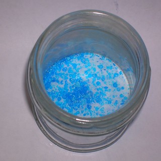
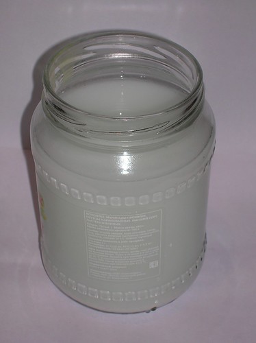
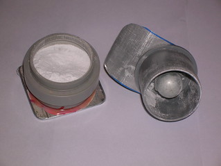
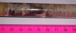
After the laser had operated for about 2 hours there appeared a foggy covering
on the output window. See Fig 5.
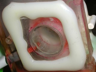
Figure 5. The foggy covering of the cuprous chloride on the output window.
The clean spot appears because this is the entrance point of the gas (helium).
The gas blows away some dirt, but it is unable to keep all the window clean.
Considering the output energy, it is too hard to be measured at this
repetition rate. Visually I can estimate the output in the best pulses to be
of the order of 100 mcJ. The output in the worst pulses is of course zero.
As the result of the experiments the harm was inflicted to:
- Two multimeters (Fired by high voltage during temperature measurements)
- Two K15-4 capacitors used in parallel with SG1 (changed to Murata)
- One glass tube (was bend when heated)
- One 5V small power supply (it had no relation to the laser, but was unlucky
enough to be too close).
28.01.2016
The tube was reassembled in order to clean the windows. In addition the tube
was equipped with two steel barrel shaped isertions having the electric contact
with the vacuum hoses. Those barrels play the role of electrodes protruding
towards the heated area but ending in 2 cm before it.
Additionally the remnants of cuprous monocloride (the one that was produced
4 days ago) was added to the load of the tube.
                            85 cm
  |<------------------------------------------------------>|
  |                                                        |
  |                         73 cm                          |
  |     |<------------------------------------------->|    |
  |                                                        |
  |     ||                                           ||
       X||X--------XXXXXXXXXXXXXXXXXXXXXXXX---------X||X
   /  |X +=======  XXXXXXXXXXXXXXXXXXXXXXXX   =======+|X|  ]
  (   |            XXXXXXXXXXXXXXXXXXXXXXXX             |  ]
   \  |XXX=======  XXXXXXXXXXXXXXXXXXXXXXXX   =======XXX|  ]
       XXXX--------XXXXXXXXXXXXXXXXXXXXXXXX---------XXXX
       XXXX                                         XXXX
                |  |        45 cm         |   |
                |  |<-------------------->|   |
                |                             |
                |           49 cm             |
                |<--------------------------->|
It was expected that this modification will give shorter discharge distance
and therefore will provide higher working pressure. Also it was expected that
there will be less dirt on the windows, because the discharge zone is now
far from them.
However in practice this have lead to further reduction of working pressure
and to shrinking of the working parameters range. With this tube I was unable
to get a series of pulses. Only single pulse at a time. Once it happened, that
after each successfull pulse, i gave it a five seconds vacuum pumping, and the
next pulse appeared to be with lasing too. This way i succeeded to make more
than ten pulses. However this trick is hard to reproduce. You need to hit
the right starting pressure, correct evacuation rate and simultaneously stay
in the valid temperature range (that had also became narrower).
One may suscpect that the new variant of the tube leaks, but until now,
it have stood overnight under the vacuum and the pressure seems unchanged.
Other possible reasons:
- The cuprous chloride is still annealing, and there will be no good lasing
until all the contaminators went out. (Need to say that the previous tube
had stood overnight under vacuum after loading and before testing. And this
one was tested immediately after loading.) If so, it is just needed to wait
and heat it in the inert athmosphere from time to time.
- The discharge length has shortened. It is presumed that in the previous case
the monochloride vapours, having gone out of the heated area, did also take
part in the amplification. And now they can't do it because there is no
discharge out of the heated area. Not only this shortens the laser active
length but also affects the temperature. Now all the active part stays nearly
at the same temperature. Earlier the flown out vapours were cooler and it
gave nealry all the range of temperature from the highest to the lowest.
If so the barrel insertions will need to be shortened.
- May be the helium has aged. The party ballooons and the car tyre aren't
the best vessels to store it. In this case the only solution to retrieve
the power is to go and buy some more helium.
- Or even the cuprous chloride has aged and the tube wants some fresh one.
- Or the spark gaps are failing. Homemade spark gaps are capable to change
triggering voltage rarely but unpredictaby, or to produce current leakage
when their body is dusted with metal. However here the gaps operate in
the easy mode: there is a large resistor in series with SG1 and SG2 with SG3
are stressed with comparatively low voltage and energy for their design,
so it is too early to expect their failure.
This variant of tube much more often gives yellow lasing. It may look like it
is overheated, but lowering the temperature gives nothing but absence of lasing.
Another notice. When it lases on both lines with the green one weaker than the
yellow one, the resulting spot has disgusting brown color. I've never seen
a brown laser before.
29.01.2016
The tube had stood 24 hoors under vacuum. The leakage appeared to be half
an inch of Hg. Then the tube got a run again. Comparatively easy and without
excessive efforts on washing it gve a good series of 20 bright pulses with
a good green and round spot. Then the temperature gone and the tube dimmed.
Further attempts to find the good conditions of lasing brought no success.
From time to time I was able to cath one green and a pair of yellow pulses,
but this is al i was able to do. The same troubles as yesterday.
So it seems that the problem is not in the annealing of the cuprous chloride.
Moreover it has again fried the multimeter being used im measurements of the
temperature. Its temperature channel had died long ago and since that the
temperature was measured my millivolts given by the thermocouple. The
calibration factor was earlier found to be 1 mv (indicated by this multimeter)
per each 50 degrees of additional heating. Earlier the temperature equilibrium
between heating by the heater and cooling by the ambient air was at 7 mv
(7*50+25=375oC). Now the equilibrium temperature is indicated as 5 mv. It is
doubtfull that the power of the heater has changed. It is aslo doubtfull that
the cooling ability of the ambient medium has suddenly increased. It means
that the multimeter began to lie. (I.e. it could lie successfully before this
event too, but the degree of its error has definitely changed). I should
warn You at the very beginning: i dint bother to calibrate the thermocouple
by the water boiling and melting points and by the lead melting point too. The calibration factor, mentioned above, was measured by using another
chinese multimeter (being presumably in good condition).
At last this semi-dead laser tube was blown with nitrogen.
Instead of the (automotive) tyre with helium anothe tyre with nitriogen was
attached to the inlet of vacuum system.
From the pressure of less tahn 1 torr the tube was then filled up to 10
inches of Hg. And with slow outpumping a search for the lasing was made. I
succeeded to catch 2 pulses at the yellow line. They appeared at very low
pressure - just before apearing of the strata in the discharge.
The tube was again filled up to 10 inches of Hg. And again during the
outpumping I was able to get a pair of yellow pulses.
Then the tube was completely washed with nitrogen by means of filling it
up to ambient pressure and evacuating two times. After that I was unable to
get any lasing (may be was too impatient). I cannot say for sure whether
the nitrogen is gulty for that or the tube has dead finally. During the
previous two tests the tube could contain some helium (remnants from the gas
pipes).
The temperature when the lasing on the nitrogen-containing mixture was
possible did correspond to 4.5 mv on the sick multimeter. If we take that
its 5 mv were equal to the previous 7 mv, then (4.5*7/5)*50+25=340oC. The
temperature range with nitrogen was very strict. However due to the multimeter
failure and unknown percentage of helium those results should be taken with
a grain of salt.
Why I am writing the doubtfull results here? Certainly not to stress the
difficulties. First of all web report is not the science paper and it is not
even a guide. This genre allows description of mistakes and fails. The
doubtfull data are important to be marked as doubtfull, however. Moreover the
web report style does even presume that the more details the better (the
healthy laziness argues opposite, though). The exemplary ones are the web
reports of Jon Singer. They are finely detailed and those details are just
interesting. I call them "science detective" for myself.
Anothe reason is that if i lost an ability or desire to continue the work on
this file, those doubtfull details may become a unique source of information
for those, who want to reproduce my variant of the laser.
Particularly I really didnt want to write about the results given by this
last modification of the laser tube. Neither it completely refuses to work
but it behaves rather "hasrd", so to say. The protruding barrel electrodes, the
upgrade, that was meant to make things better, appeared to make them much worse.
And one should be aware of this if trying to make such a laser.
01.02.2015
The deeds of this weekend:
- Lasing with pure nitrogen as a buffer gas has FAILED
- Lasing with a "open Blumlein" driver has FAILED
- The cuprious chloride was made of CuSO4 and NaCl successfully
- Lasing with a driver based on an alumina filled spark gap was successfull.
And now the details.
NITROGEN
The tube was loaded with a fresh batch of CuCl. And got a run until more or
less stable lasing was got. Then the vacuum system was connected to the tyre
filled with technical grade nitrogen. The system was washed by the nitrogen by
triple filling to the ambient pressure and evacuating.
Then it got a test run. Several times I crossed all the reasonable range of
pressures (0.1..20 torr) and all the available temperature range (0..350oC).
Each time with different steps. Used the gasostatic and the slow flow modes.
No effect. NO SIGNS OF LASING AT ALL. The nitrogen itself didn't lase also.
Then the vacuum system of the laser was connected back to helium. Washed
with gelium four times (again by filling up to the atmospheric pressure and
evacuating back to <1torr). Then the tube got a control run. After rather
serious attempts i was able to a pair of pulses wih lasing but thats all.
The operational ranges of the pressure and temperature became very strict and
performance degraded seriously.
Since the fact that the lasing almost has not returned, it seems that the
nitrogen somehow poisons the cuprous chloride poweder.
The tube was opened and loaded with a new fresh batch of CuCl. The consequent
test run (of course with all the correspondent actions, like washing with
helium and so on) has shown an excellent lasing. It proves to some extent that
the powder was mutilated, most probably by the nitrogen.
Here i should add that i have never allowed the tube to be heated while the
air was in there. Maybe it is the excessive precaution, or, looking at the
results with the nitrogen, maybe not.
Generally I should say that the theorem of existence can be much more easily
proven than the theorem of inexistence. If i got a lasing in some conditions
it undoubtfully means that the lasing is possible in these conditions. If I
didn't get the lasing in some conditions it means only that I did not get
any lasing. Nothing more. ...May be I am not skilled enough...
Actually the system is tolerant to some amount of nitrogen addition to
the helium. However this contamination should be reasonably small. From time
to time I observe some violet spot at the place, where the laser beam hits the
paper. I tend to explain this by lasing of the N2 at 428 nm. They say this
takes place only at a strong dilution of the nitrogen with helium and here
are exactly those conditions. On the other hand it may be some other line
of someting else. There are dozens of them and if Your gas mixture is not
extra pure, You can not affirm anything.
"OPEN BLUMLEIN" type of pulse forming circuit
           Cp1
          470 pf

      +-----||-------+
      |              |      Rs2 8.3 M
  (-) |              |
   0--+-----I (------+----/\/\/\/---------------------+
      |              |                                !
      |     SG1      |                                !
      |     10 mm    /                                !
      |              \ Rb1                            !
      |              / 16.8 kOhm                      !
      |              \                                !
      |              /                                !
      |              |                                !
      |              |       LT1                      !
      |              |    /--------\                  !
      |         +----+----|o  x   o|-------+-------+  !
      |         |    |    \--------/       |       |  !
      |     SG2 |    |                     |       |  !
      |    7 mm |    |                     / Rs    |  !
      |         U   ---                    \ 200k --- !
     ---            ---                    /      --- !
     ---        -    | Cs1                 \   Cs2 |  !
      | Cs0     |    | 2nf                 /   4nf |  !
      | 30 nf   |    |                     |       |  !
      |         |    |                     |       |  !
   0--+---------+----+---------------------+-------+--+
  (+)
Fig 5. The pulse forming circuit of the "Open Blumlein" type. The
designations are exactly the same as on the figure 1.
Concerining the idea of double high voltage pulses needed to feed the
copper halide lasers I always wondered whether the necessary concentration
of the neutral copper atoms can be provided just by simmering with a constant
(direct) current.
If we assume that the "power" of both pulses may be equal, we can estimate
the necessary strength of the simmering current. Lets just divide the integral
of the current over the pulse by the duration of the time interval between
the pulses. In other words lets divide the charge, having been accumulated
by Cs2, by 200 mcs: 4nf*(2.6kv/mm*5mm)/200mcs = 260 mA.
If we then multiply this value by the estimated voltage drop over the laser
tube (lets take it as 10 kV) we will get that the DC simmering will eat as
much as 2.6 kW of power. Even more than the heater does! It is rather difficult
and annoying to erect a power plant for just the simmering, so there should
be another way.
Anyone, who played with an open air nitrogen laser, knows that if we forgot
to put a resistor (or a coil) between its wings, there appear two pulses. The
first (sparky) one is when the opposite wing is charging and the second
(lasing) one is when it is discharging. This might become a good prepulsing
technique. So i decided to give it a try.
A circuit as shown on the figure 5 was assembled. It helps that most of the
parts can be kept intact from the previous scheme. It takes onle several
reconnections and sevral parts should be moved from one place to another.
For example the SG3 spark gap was only turned to its maximal spacing. I did
not even bother to remove it.
In order for not to mess the results the tube should be surely operational.
To ensure this it was again loaded with a fresh cuprous monochloride. The
payload appeared to be unsuccessfull. Some powder appeared to be wet, and
another part of it just dropped out of the tube. Finally the tube was fully
reassembled and cleaned with a drawbolt. Additionally its barrel shaped
electrodes were enshortened. Now the distance between them and the heated
zone is 7 cm.
After the cleaning, modification and reloading the tube was tested with
the previous (fig 1) feeding circuit. Only after the reliable lasing had
been obtained the feeding circuit was reconfigured into the one shown on
the figure 5.
Concerning the measurements of current: the expected current in the
dissociation prepulse is several hundreed of milliamperes, and the current
in the laser pumping pulse is several hundreed of amps. I had no illusions
about registering together the two pulses differing in amplitude by almost
three orders of magnitude, especially with the strong interferences. So here
is only the calculated trace of the current in the tube:

Figure 6. The calculated current in the laser tube when the "open Blumlein"
circuit triggers. 1 mv on the picture corresponds to the 10 mA of current.
The result is NO LASING. Again I did my best to scan the ranges of the
pressure and temperature. All in vain. Also the scheme has shown itself to be
unstable. When the spacing in the SG2 is low enough (5 mm or less) it triggers
reliably, but the scheme at these settings behaves not the way I want. (It
produces too low charge in Cs2 and too strong current just before the moment
of the laser pulse) On the contrary when the spacing in the SG2 is large
enough, the scheme should work as desired, but the SG2 oftenly and unpredictaby
refuses to trigger. Nevertheless I've tried different settings of the SG2 to
SG1 ratio (each setting with scanning of pressure and temperature) and still
no lasing.
The scheme was then rearranged back into the "double RC-circuits" double
pulse driver (fig 1.). The sparks gap were set to their nominal spacings
(SG1=10mm, SG2=4 mm, SG3=5mm) and without excessive efforts the tube did lase
successfully. It means not only the fact that the simmering technique fails
here, it also means that the sheme, sown on the fig 1, has decent
reproducibility. The parts have been moved and replaced, the spark gaps have
been turned towards and backwards, and when all the things were restored to
the designed (not certainly to the original) positions the laser became
operational again. Moreover, now, when the sircuit has worked for quite a
while, I'd say that the percentage of triggering failures has dropped
significantly.
Interlude 2. COPPER MONOCHLORIDE IN LARGE QUANTITIES.
As You might already note, the laser eats the chemicals like a behemoth.
And the nice old glycerol way of CuCl production becomes less and less
satisfactory. (Besides my stock of the CuCl2 has been exhausted). Here is
something like "mix a barrel of one thing and a bag of another thing" needed.
And the necessary receipe has finally been found and adopted.
This receipe utilizes the unusual property of the copper monochloride to
dissolve in concentrated water solutions of a comon salt.
The similar receipe is used for the printed circuit boards etching by the
vitriol method. However the attempts to conduct the both works together (to
etch the boards and to get the cuprous chloride) have lead to fail only. So
it was needed to make a separate try.
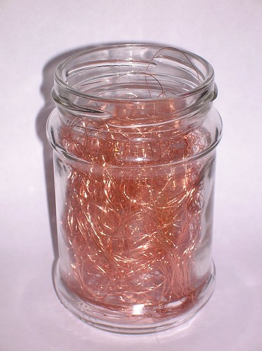
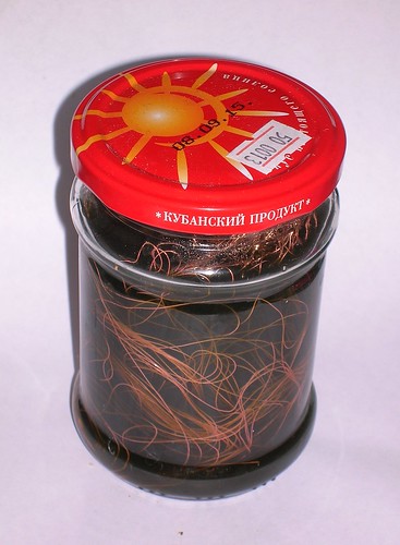
Several meters of a stranded copper wire were taken.
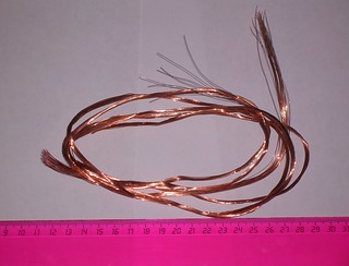
The insulation of the
wire was removed and the obtained bunch of copper wire was crumpled into some
kind of "crow nest" (in order to leave the maximum surface of the copper open).
That "crow nest" was put into a 200 ml jar and set aside.
24 gramms of blue vitriol (CuSO4 x 5H2O) and 48 grammes of kitchen salt (NaCl)
vere mixed together in anothe jar.
And then dissolved in 200 ml of a hot water
(from a freshly boiled kettke).
After the dissolving had finished there
appeared some insoluble solids (most probably the basic salt Cu(OH)Cl). The
solution was decanted from the solids into the first jar (having the mushed
copper wire inside). The precipitate from the jar where the solution took place
was discarded.
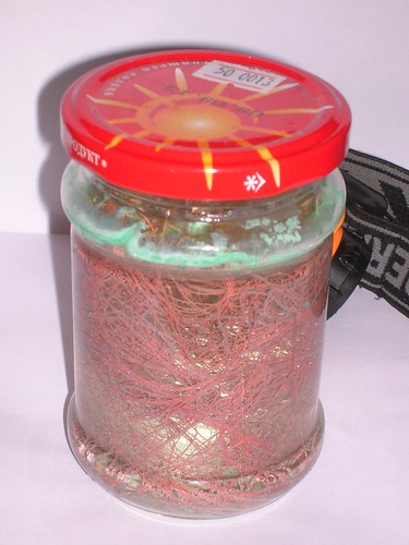
The jar, containing the copper vitriol and the kitchen salt with the copper
wire was closed tightly with its lead and set to a warm place. After 24 hours
the liquid in the jar has lost any bluish shade and became slightly brownish.
There also appeared some residue near the bottom and near the surface. (Most
probably the mentioned basic salt again.)
A new (one liter) jar was taken and filled to a half with a cold tap water.
The brownish liquid from the jar with the copper wire was then filtered into
that new jar with water through a piece of cloth. When the drops of the
brownish solution went into the excess of water there appeared a lot of
white turbidness.
The jar with the remnants of the copper wire was filled with tap water (to
prevent copper from oxidation) and set aside for future use.
The jar with the water, where the solution was poured, was let to stay over
1 hour until the residue has settled. After the hour had passed the jar
appeared to containea layer of fine grit white powder and a layer of slightly
bluish water above it.
The powder was washed with water several times, then with a 96% ethanol and
finally with an absolute isopropanol. The yield is quite large. (May be a
small coffee cup). I had no chance to weight it, because i don't want to dry
it in order to avoid the severe losses, and when it is wet, the weighting is
senseless.
The practice has shown that the copper monochloride can be sucsessfully stored under the layer of isopropanol (or even under the layer of water) for a long time. The water or alcohol should contain a small amount (~1 volumetic %) of some acid, otherwise the monochloride rapidly decomposes. Vinegar eccence suits well. Hydrochloric acid is even better here. By the way the same approach (addition of a tiny amount of acid) works well when washing the monochloride during its production. Acidifying of the washing water/alcohol helps to reduce losses.
THE ALUMINA SPARK GAP. THE NEW HOPE.
The "double RC-circuit" double high voltage pulses generator does a good job
but it wastes the enegy. Indeed when the both pulses have appeared the further
behaviour is only the full dscharge of the primary storage through the
resistors. And the energy in the primary storage must be the way greater then
the one in the secondary storages, otherwise there would be severe voltage
drop and the scheme would be inoperational.
But maybe we could use the remaining energy for further production of the
laser pulses? In this case the laser would produce a bunch of flashes per
each primary storage discharge. Such a way of operation they call the "burst mode".
The only thing that is needed to make the burst mode possible is a low
inductive high voltage switch, capable for triggering several thousands times
per second. An affordable solution was found in the work [H.Saito, H.Taniguchi,
H. Nozava, K. Owashi. Simple and compact neutral metal vapor laser assembly
operating in a low temperature region. Rev. Sci. Instrum, 56 (1985) No 12
2248-2250]. They used a spark gap with a very narrow spacing and additionally
blew it through with a pressurized air. Others use hydrogen thyratrons, but
those are expensive and require complicated drivers (sensitive to the damage
by high voltage leaks in most cases).
Another thing was found as a byproduct of my investigation of lasers with
carborundum electrodes. Jon Singer had noted, that the electric discharge
through the porous medium can have the fast recovery time, and mailed me
about it. I cannot say, that I haven't thought this way independently of
Jon's letter, but my thoughts had not take a form of text or either a form of
a device, so the priority does definitely belong to him. Actually the
possibility to test the invented type of the switch with the copper halide
laser was one of the three main reasons, that made me to build the latter.
           Cp1
          470 pf

      +-----||-------+
      |              |
  (-) |              |
   0--+-----I (------+-----------------------------+-------------+
      |              |                             |             |
      |     SG1      |                             |             |
      |     10 mm    /                             /             /
      |              \ Rb1                   Rb2   \             \ Rs2
      |              / 91 kOhm             91 kOhm /             / 8.3 MOhm
      |              \                             \             \
      |              /                             /             /
      |              |                             |             |
      |              +-----------------------------+             |
      |                                Cs2 4nf ||  |             |
      |                               +----+---||--+----+        |
      |                               |    |   ||  |    |        |
      |                               _    |       |    | SG3    |
      |                              /o\   / Rs    |    | 5 mm   |
      |                          LT1 | |   \ 5k6  ---   U        |
     ---                             |x|   /      ---  XXX       |
     ---                             | |   \   Cp3 |    -        |
      | Cs0                          \o/   /   470 |    |        |
      | 30 nf                         -    |    pf |    |        |
      |                               |    |       |    |        |
   0--+-------------------------------+----+-------+----+--------+
  (+)
Fig 7. The "relaxation oscillator" type driver circuit for copper halide
laser. Parts designations are kept the same as on the figure 1.
The new driver schematics is shown on the figure 7. The ballast resistors
Rb1 and Rb2 with the secondary storage capacitor Cs2 and the spark gap SG3
form a classical relaxation oscillator with a pulse repetition rate of the
order of the RC time constant (4nf*91KOhm/2)=182 mcsec. The primary storage
Cs0 is needed only to provide the sufficient power for this relaxation
oscillator to operate. If I had a very powerfull high voltage power suppy,
and if the SG3 spark gap is sufficiently strong to endure the power, the
scheme could operate continiously, resulting in a very powerfull beam. In
the present form, however, the circuit does only produce bursts of pulses.
The pulses in the burst are separated by the interval that is mainly
determined by the RC time constant of the relaxation oscillator, and the
period between the bursts is equal to the time of primary storage charging.
The latter is quite large because i use a low power high voltage supply.
The specific feature of this circuit is of course the SG3 spark gap design.
In the preliminary tests it was made of two dremel bits having an alumina
(Al2O3) ceramic abradant endpieces. See fig 8.
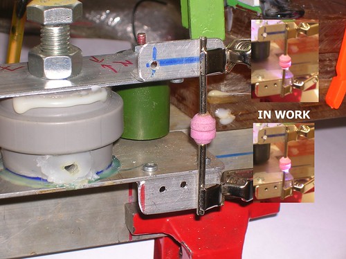
Fig 8. The design of the new spark gap having the gap filled by porous
Al2O3 ceramics.
Since the spacing between the electrodes of the spark gap is filled with
the porous dielectric, the spark is forced to be as narrow as needed to come
through that pores. The thin spark has three properties:
- It cools faster.
- Its plasma recombinates faster.
- It has greater resistance.
The first two properties are very usefull here, but the third property
could waste all the bonuses, if the resistance is large enough to slow down
the pulse and to diminish the pumping energy.
So the main question was: whether the copper laser would agree to lase with
this scheme and this spark gap or not.
The answer is YES. It lases. Maybe not as reliably as it does with the "double RC-circuits double HV pulse generator", but still does. In the best
pulses its spot is far brighter than the one with the double pulse generator.
Obviously there are several pulses in each burst and their energy sums when
perceived visually.
Need to say that with the exclusion of the only one test run, where the
laser was specially tested for the capability to operate with an output mirror
consisting of two glass plates glued one to another, all other runs, mentioned
above in this file, were made using the resonator formed by a concave aluminium
mirror (first surface) and a planar mirror from some unknown He-Ne laser.
The transparency of the latter in green spectrum is about 50%. For the yellow
line it is less transparent.
So now I can say for sure that the spark gap with its inter electrode spacing
having been filled with a porous dielectric is definitely able to drive up the
copper halide laser. Refer to the video below. The voltage of the ceramic spark
gap self triggering was equal to the self triggering voltage of an air filled
spark gap with a spacing of ~5 mm.
The lasing is a bit unstable, and it feels like the spark gap degrades
gradually. However when it was opened, there were no signs of degradation.
Lets wait and see.
By the way. When working with this spark gap the temperature range of
successfull laser operation have moved upwards. By almost 50 degrees.
02.02.2016
THE STEP NEXT. THE SALT SPARK GAP
A new spark gap have been made. Its design is exact copy of the already used
SG1..SG3 parts of the schematics. The only difference that its body was filled
by a powder of the common kitchen salt. Don't even think that the salt was just
the first thing, my sight fell upon. I know well that every dielectric will
like to decompose when in touch with a star-hot flame of a spark. Some of them
(like carborundum or the common glass) decompose to conductive things (carbon,
silicon, metals) and it makes the dielectric to fail. On the other hand the
kitchen salt consists only of sodium and chlorine. And it is very doubtfull
that the sodium will stay in the form of metal for a noticeable time after the
salt has decomposed (This case will be pleasant too, I'd be happy to find a way
of an easy production of the sodium metal.) It should go through the oxidation
instantly, and the resulting sodium oxide is dielectric not worse than the
initial kitchen salt.
I've grinded about 50g of kithen salt in a kithen pounder. (And while I was
doing that I was full of doubts If I was doing something wrong. Indeed if the
grains of salt are too small it gives too narrow pores. Resulting maybe in too
high resistance of the spark. Some imp however made me to continue the job to
its end.)
Then the fine grit powder of the kithen salt was poured into the plastic body
of the spark gap. The level of the powder layer was just enough to fully cover
the round head of the top electrode, meaning that all possible ways for the
spark are coming through the layer of the salt powder.
The spark gap, having been filled with salt, was then finally assembled and
installed in place of the SG3 (refer to fig 7.) The initial spacing in the
spark gap was set to 5 mm.
The tests for self triggering voltage have shown that the spark gap requires
unusually large spacing between its electrodes to self trigger at reasonable
voltages. Finally I succeeded to tune its self triggering voltage to 13 kV
(corresponds to 5 mm of spacing in air filled spark gap). And when i did so
the laser agreed to lase. The series of lasing bursts vere long and strong,
and i've never seen a yellow spot with this spark gap.
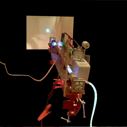
Fig. 8. The homemade copper halide laser with the salt filled spark gap
in operation.
Need to say that the upper border of the range of operational pressures has
shifted towards the high pressure. The top pressure, I was able to see the
lasing, was as high as 1 inch of Hg.
To make a checkpoint I removed the fine grit salt powder from the spark gap
body and filled the latter with a kitchen salt just in the state it was sold.
Note, however, it was not the type of salt that has comparatively large
crystals, it was the type of salt, that has tiny grains, for use in
saltcellars. The test run has shown, that the laser does lase... From time
to time. There were sibgle bursts only. No series at all. Rarely the spot was
very bright, but the average... Generally the things are bad when the particles
are too large.
It means that the powder for the spark gap filling should be as fine grit as
possible. The new name for the method: "The high repetition rate spark gap
having its inter electrodes spacing filled by a dielectric nanomaterial."
06.02.2016
After the tube had again refused to work. I decided not to refill it only, but also to clean it thoroughfully. However something went wrong and the tube cracked. Here is how it looks from inside.
  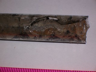 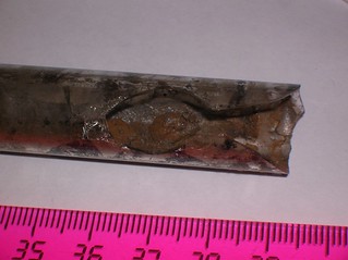 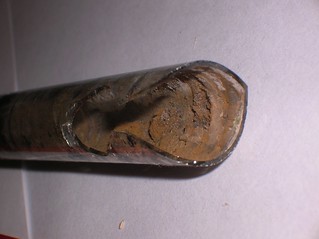 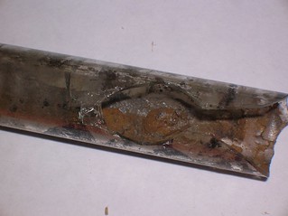 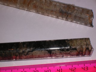 
The tube was in operation for about six hours total. Other details later.
8.02.2016
This weekend deeds:
- For the replacement of the old laser tube a new one was assembled
- Got the snapshots of the yellow and green lasing lines split by prism
- Got rhodamine 6G lasing under the beam of the copper laser
The details are foregoing:
TOTALLY NEW TUBE
Initially it seemed that there's no need to clean the tube thoroughfully
each time. It seemed that one can only add a fresh portion of the cuprous
chloride and seal the tube again. The argumentation was that the remains of
the old cuprous monochloride become tightly attached to the walls of the glass
tube forming rather evenly distributed layer on the glass. Further on, however,
it became clear, that the old cuprous chloride does not help lasing. Somehow
it looses its "activity". One can suppose that its flowed surface has its
pores sealed, so the area of vaporization surface becomes small. Another guess
is that it reacts with nitrogen or oxygen contamination and becomes sealed in
the bulk of cuprous oxide or mayme even nitride. One way or another but the
thing, that looked good intitally, has finally turned to be bad, In addition
after a few loading procedures the tube becomes uncleanable. As You've seen
above the old laser tube has crushed. Just in the middle of an attempt to
clean it.
There was no choice but to build a new one. Of course the main structural
parts, like nichrome wire, thermocouple, metal hoses and glass windows were
recovered and reused. The asbestos cord, however had become unusable and was
discarded.
I think that the design and assemblage of the tube are pretty straightforward
and need no comments. However there are two hints:
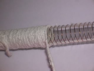
- When winding the nichrome wire onto the glass tube, the wire will tend to
slide. Generally it is the very bad tendency, because it can shorten the turns
and make the heater to fail. To avoid this strech two or three asbestos threads
along the glass tube (as shown on figure 9.) You can fix the ends of the
threads even with a sticky tape. And when You will wind Your wire onto the
glass tube, the threads will keep the turns from sliding, helping You greatly.
- Seal the tube as tightly as You can. Act as if You did if trying to make
a completely sealed off laser. Since the operational pressure is quite low, and
since the laser does not like the nitrogen and oxygen, every torr per hour of
an additional leak will make You crazy. Do Your best in eliminating every leak,
You can find.
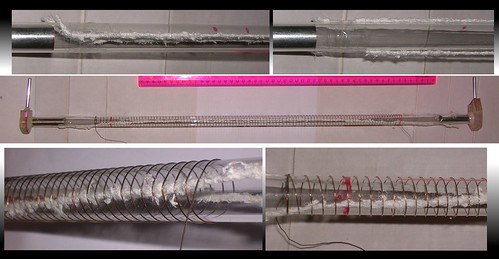
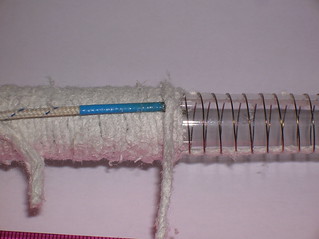
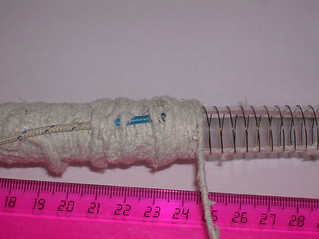
Fig 8. The aid for winding a metal wire over a glass tube. Just stretch two
threads along the tube and wind the wire over them.
When loading the tube with a fresh cuprous chloride it helps to wet the
substance with a little amount of alcohol. This way it becomes a bit sticky
and keeps itself on the walls of the tube during the drying process. When
the powder is put into the tube use a heat gun to dry it quickly. Set the
heat gun to 100~120oC and blow the hot wind through the tube for 20..30 min.
Don't make the wind too strong. Otherwise You may blow Your powder out of the
tube.
So finally the tube was assembled, filled with some cuprous chloride
(obtained by vitriol method) and tested. The tube was evacuated to less than
1 torr, filled with helium, and heated. At first there appeared some
unpleasantly looking fumes, resembling the ones observed in tests with cuprous
iodide. Indeed the cuprous iodide decomposes heavily when the helium is
contaminated by air (oxygen), or when samples of the salt are contaminated
with copper dichloride. Iodine fumes pollute the tube, the pipes, the hoses,
and even make hazard to the vacuum pump itself. Their brown color interferes
with lasing and so on.
In this case the cuprous chloride might be contaminated with iodide if
using a iodinated kitchen salt in the process of its production. Fortunately
the contamination was not very strong and a bit later all the bad looking
brown fumes were successfully sucked off by the vacuum pump.
After a few washings with helium with gentle heating, the tube agreed to lase.
At first the laser spots appeared rarely, but the more cycles of heating and
helium exchange, the more oftenly this spot appeared.
The tube appeared to be operational from 4 to 10 mV indicated by the
multimeter being connected to the thermocouple. When reassembling the tube I
made a test run of the thermocouple - by putting it into a flame of a butane
torch. The hottest place gave 41 mv. The other multimeter showes 1350oC in
the same conditions. In the literature I've found that Bunzen's torch has
the flame as hot as 1230oC and Bartel's petrol lamp has the flame as hot as
1380oC, so the figure, i got, looks trustworthy. If we then assume that the
voltage does linearly depend to the temperature, we can get a calibration
factor: k=1350/41 mv = 32 oC/mv. (We neglected the room's 25oC on the high
temperature background. The result is not comparable with the previous one,
however, because the multimeter was changed again.)
Now we can estimate the minimal temperature Tmin=k*4mv+25=155oC
And the maximal temperature: Tmax=k*10mv+25=345oC
The unusually low Tmin puzzles myself. I guess it is due to the fact that
the vitriol method cuprous chloride has a form of a very fine powder and has
a very large surface of vaporization. Such a low temperature of operation
can only be observed in the first few runs of the tube. With annealing the
lower border of operation grows rapidly.
The temperature of optimum, seems to be rather stable however and
corresponds to 9+-1 mV indicated. (9mV*32oC/mv+25oC=313oC).
The tube was tested with different pumping circuits and lases best when
accompanied with a salt filled spark gap (see above). The further described
results are obtained with the pumping circuit based on the salt filled spark
gap.
Oh, almost forgot to say: yet another reason to clean the tube every time
is that the sediment on its walls is partially conductive. And it becomes
more and more hard to get a glow discharge while it accumulates. It tends
to have a form of multiple tree-shaped arcs along the walls of the tube rather
than a form of a uniform column of glow. When You feel You need to reduce the
pressure in order to get a good glow, it definitely means Your tube requires
cleaning... but it may be a bit too late.
THE YELLOW AND THE GREEN
It is well known that the copper vapour laser lases at two lines of spectrum.
Its most powerfull line lies in green and its secondary line lies in yellow.
It is interesting to observe them both, however usually the green line hides
the yellow one due to the excess of power and brightness.
I've got a prism, made of some heavy (and yellowish) glass. It has a strong
dispersion, so the experiment on observing both of the copper laser lines looks
like a good job for the prism.
The prism was installed in front of the copper laser and after a few attempts
the new place of the laser spot was found.
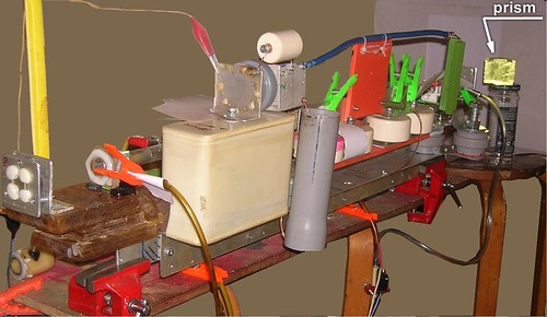
It was an uneasy task but finally I
succeeded in taking a video of the spot, refer to figure 9 and video below.
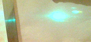


Figure 9. The spot of the copper laser beam split by prism into the green
one and the yellow one. Due to the main spot is too bright this fact is better
seen on the secondary spot upwards and rightside to the main one.
The fact that the beam can really be split into the bluish-green one and
the yellow one is the serious argument for the statement that here I observe
the lasing of copper and not some other thing.
The space between the prism and the paper screen was about 1 meter. Was it
larger the spots could probably be fully separated. But I have a limited room
for my experiments. Sorry for that.
PUMPING A DYE LASER

Another thing the copper laser might be usefull for is the pumping of some
dye laser. However unlike nitrogen laser, widely used for these purposes, the
copper lases in green an hence unable to pump violet and green dyes. The choice
is probably limited to rhodamine only. The apparatus was set up like it takes
place when using a nitrogen laser to lase the dyes.
A typical 5 ml spectrofotometer cuvette (with two mat faces having been
polished at home) was filled with a solution of rhodamine 6g in isopropanol.
The beam of the copper laser was focused onto the cuvette by a cylindrical
lense having the focal length of 20 mm.
In a few first tries there was no lasing. Then one side of the cuvette was
equipped with an aluminium coated mirror (just a piece of the common flat
household mirror) and the opposite side of the cuvette was equipped with
a microscope coverclip to increase the reflection. Both mirrors were just
glued up by a few drops of a hot glue.
The laser then got another run.
Imagine the job. When its heater is on it takes only two minutes for the
laser to cross the whole temperature range of operation. And maybe 30 seconds
for its optimal part. (It takes only a bit longer when cooling.) Moreover,
when I let 25 torr of helium in, and set the vacuum line to a slow evacuation
it takes about a minute to go over the full range of pressures where the laser
is operational. A bit less than 20 seconds for the optimal part of this range.
And when I'm jumping between valves and switches as a monkey it is also needed
to adjust the position of the cylindrical lense and cuvette. I won't keep it
in secret - i was helped in there. And newertheless it was hard to get some
good pulses and to take a snapshot. No surprise that i haven't even seen the
spots of dye lasing by my own eyes. They were only discovered when watching
the video record taken by my camera.
And the lasing of the dye was finally observed (refer to figure 10 below).
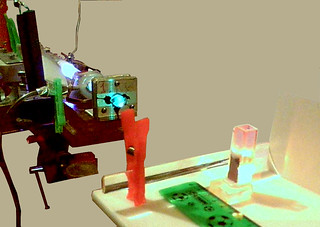
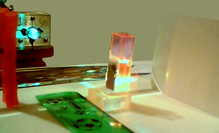
Figure 10. Rhodamine 6G lases under the beam of the homemade copper vapour
laser.
The fact that the lasing of a dye laser can be achieved here does prove my
visual estimation of the output energy (~100 mcj). One can argue that nitrogen
laser having 100 mcj can do the job without any aid of any lenses or mirrors,
but let's make a disount for the fact that typical copper vapour laser pulse
duration is 100 times longer than one of the TEA nitrogen laser and the fact
that the beam of the copper laser is large and had to be focused. (Actually
since the TEA nitrogen laser's pulse is shorter than the lifetime of the
upper level of the dye, we should compare not the pulses of both lasers, but
the duration of the copper laser pulse and the lifetime of the rhodamine. The
later ratio will be 12 to 25 only. And this value does better correspond to
the degree of focusing here.)
One can (and already did) note that the laser needs smooth (or better - fully
authomatic) controls of temperature and pressure. For the temperature it sounds
reasonbly. Maybe a dimmer in series with the heater would help. However I'm not
sure that it will survive in the conditions of often high voltage hits from the
plasma to the heater spiral through the capacitive coupling. The things with
the pressure are even worse. The vacuum electrically controlled valves are not
only expensive, thy are also cumbersome. And the pressure control units will
suffer from the same problem of high electromagnetic interference.
Those ones, who want the complete solutions, I should warn that from the
very beginning the task of designing of the temperature and pressure control
automatics was not considered as the goal. I have already known almost anything
I wanted to know about the DIY copper halide laser. I've tested almost any
thing I wanted to check here (and in the first order - the applicability of the
novel types of the spark gaps). And the project approaches its end (the
triumphal putting onto the shelf or rearranging into another laser type). And,
I suppose, I will be capable to use the hand controls of the temperature and
pressure for the rest two or three weeks.
CAPILLARY SPARK GAP
The salt filled spark gap is good. But first of all it shouldbe shaken from
time to time to awoid caking of the powder (it reminds the Marconi-Popov's
coherer receiver). And also it requires changing of the powder, since it tends
to become contaminated by the electrode erosion products (read - by powdered
iron and iron oxides). Secondly it is not clear how to avoid overheating when
rising the repetition rate.
On the other hand the porous filling of the spark gap is not the unique way
to force the spark to be thin and fast reacting. One may, for example, use a
thin capillary.
Here it is a good place to remind that the laser on the copper halides (or
compounds other than halides) requires for its operation that some part of
copper be in a form of free atoms. I.e. some part of the copper salt must
be decomposed (good if reversibly). The fathers of that type of lasers
arleady in early ages had proposed to use the electrical discharge to
decompose the salts. From that times the copper halides laser is fed by either
double electrical discharges or by the continious series of pulses. And
each previous pulse provides the necessary copper atoms for the consequent
one. The time delay between the pulses should not be very small, or else
the lower laser level of copper will stay be populated and there will be no
lasing at all. On the other hand the delay should not be too long, or else
all the free atoms will recompose into the salt or (which is much worse)
will sediment on the walls of the tube, forming a conductive coating, that
can effectively shorten the discharge. The required delay time is well known
to anyone, whoever wanted to build a copper vapour laser, and have bothered
to look at least into Sam's Laser FAQ. This is 100..200 mcsec.
So our fast switch have to deal with 100..200 mcsec delay times. The
processes acting in its recovery may include cooling of the plasma, ion with
electron recombination, gas exchange and so on. Because we are going to
consider a capillary type spark gap, we can readily neglect the gas exchange.
There are still thermal and recombination time constants.
Considering the thermal side of the question, one can easily obtain the
next expression for the difference of temperatures between the center and the
border of a long cylinder having a volumetic heat source q evenly distributed
inside it:
deltaT=q*R^2/(4*lambda)
Where R - is the radius of the cylinder, lambda is the heat conductivity of
its material. Lets consider a part of this cylinder having the length of l.
And lets multiply the nominator and denominator of the expression above by
the volume of this part of the cylinder (by pi*R^2*l):
deltaT=pi*R^2*l*q*R^2/(4*lambda*pi*R^2*l)
Lets then note that pi*R^2*l*q is exactly the full heat source acting in the
considered part of the cylinder. Lets designate it as Q:
deltaT=Q*R^2/(4*lambda*pi*R^2*l)=Q/(4*pi*lambda*l)
This defines a thermal resistance of this part of a cylinder as:
Rt = 1/(4*pi*lambda*l)
may be with a precision of a factor of two due to the fact that the average
temperature is less than the temperature in the center.
The heat capacity of the concidered part of the cylinder is
Ct = cv*pi*R^2*l
where cv is the specific heat capacity of the material (gas) per unit of
volume.
Further on, using the analogy between the heat capacity and the electric
apacity and between thermal resistance and electric resistance we can readily
write the time constant:
tau = Ct * Rt = cv*pi*R^2*l/(4*pi*lambda*l) = cv*R^2/(4*lambda)
A mole of diatomic gas has thermal capacity of (5/2)r, where r=8.3 J/(mol*K)
is the universal gas constant (Sorry, but the capital R is already occupied by
the radius of the cylinder). Thus in MKS for atmospheric pressure:
cv=20.75[J/(mol K)]/22.4e-3(m^3/mol) = 926 [J/(cub.meter*K)]
Looking for the heat conductivity of the air or nitrogen I mysteriously faced
tons of misprints in handbooks. Finally I decided to use a value for oxygen
[Chemical Encyclopedia. In 5 volumes. Under the edition of I.L. Knoonyants.,
Moscow. Sov. Encyclopedia, 1988, vol2]: lambda(O2)=0.0245 W/(m K).
Finally for a tube having 1 mm bore and filled with 1 bar of air we get
tau = 926*(5e-4)^2/4/0.0245 = 2.36 msec
It is too large for our purposes. To come down to the needed values we can
use helium or hydrogen, having the heat conductivity higher by an order of
magnitude. Alternatively we can use reduced pressure in order to reduce the
specific heat capacity. E.g. at 100 mbar one mole of gas will occupy not 22.4l
but 224 liters, giving cv = 92.6 [J/(cub.meter*K)] and thus tau = 0.236 msec.
Yet another way is to further reduce the radius.
The values we got show that the necessary performance of the spark gap can
be obtained with capillaries having less than 1 mm bore and filled by the
common air at less than 100 mbar. At least from the thermal point of view.
Maybe the finite speed of recombination will add some correction to the time
constant too, but for now i'm out of constants to estimate it. Nevertheless
the correction should be relatively small since the typical time delays of
preionization in TEA lasers are less than several microseconds. It makes me
think, that the recombination times are neglible when compared with time
intervals needed here.
The obtained values do not seem to be unreachable and the capillary type
spark gap begins to seem worth of trying.
Interlude 3. Artisan Technologies. Glass Blowing. CAPILLARIES.
The glassworking arts give much of eyecandy... and feeling that You can not
do the same. However the things aren't as infernal as it seems at the first
glance. To make a capillary is not more complicated than to bend a glass tube.
You will need a common butane torch and a (large) stock of glass tubes.
Take a glass tube (5..10 mm in diameter). Keep the tube in Your hands and
try to rotate around its axis. When You are confident with the rotation
technique, begin to heat the tube by the butane torch. Continue to rotate the
tube. From time to time check the elasticity of the tube by smooth pulling
it along its axis. When it starts to yield, rapidly get it out of the flame,
wait a bit and pull it along its axis by a single and strong motion.
The length and diameter of the obtained capillary depend strongly to the
delay between the moment, when You got the tube out of flame, and the moment
of pulling. The length of the capillary depends also to the width of the
heated area of the tube. This way You can control the length independently
of its diameter.
It requires some training, so You better have a good stock of suitable tubes
within reach. However there is nothing impossible. Don't give up and finally
You will get a feeling how the heated glass behaves.
Once You became familiar with the technique it will give You practically
unlimited source of the full range of capillaries: for sealing Your vacuum
systems, for making the pocket-sized dye lasers, for plasma tubes and spark
gaps. And moreover it is just...fun.
Back to our problems. A few capillary spark gaps were made. Their bore varied
from 0.5 mm to 2 mm and their discharge length varied from 50 mm to 170 mm.
See fig 11. The construction of capillary spark gap is as simple as possible.
It uses a glass tube having capillary part in the middle. The wide endings of
the tube are equipped with electrodes (some screws with their heads directed
towards inside the tube). In addition to the electrode one end of the tube is
equipped with a glass capillary pipe for evacuation and further sealing. The
bolts (electrodes) and the sealing hoses were sealed in with a hot glue. Not
a permanent solution, but good for a month or two of the sealed off operation.
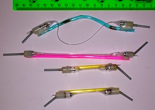
Figure 11. Capillary spark gaps of various types.
The pressure inside the spark gaps was specially choosen to set their self
triggering voltage to around 13 kV. The schematics used for these purposes is
shown on figure 12.
  o---/\/\/------+-----+-------+
                 |     |       |
      8.3 MOhm   |     |       |
                ---    V SGA   V SGB
                ---
             4nf |     ^       ^
                 |     |       |
  o--------------+-----+-------+
Figure 12. Test circuit for choosing the pressure in the capillary spark gaps.
SGA - air filled spark gap of the round-to plano type having 5 mm of spacing
between its electrodes. SGB - the capillary spark gap being tested.
Attach the newly built capillary spark gap to the test circuit (fig 12,
position SGB), and attach its filling hose to the vacuum system. Then evacuate
the capillary spark gap and turn the test circuit on. If the vacuum good enough
it provides that only capillary spark gap triggers. Gradually rise the pressure
in the capillary spark gap. Note the moment when it stops to flash and SGA
begins to trigger. Then set the pressure in the capillary spark gap to be
90% of the noted pressure (pump away 10% of air). Then let the capillary
spark gap to flash for a while. If its triggering voltage seems to be stable
seal it off. To do this just heat its glass filling hose by a flame of a gas
torch. The atmospheric pressure will then do all the job for You - it will
compress the heated glass and form the vacuum tight sealing.
If the triggering voltage floats during the training it means that it is too
early to seal the capillary spark gap off. Cycle evacuation. filling and
training procedures until the triggering voltage stabilizes. If it refuses
to stabilize, it is possible that the capillary spark gap should be reassembled.
Be carefull during the tests - don't overheat the capillary spark gap. They
are very sensitive to the heat and fail oftenly due to this reason. Usually
the capillary part breaks. The series of pulses should be short enough to avoid
overheating.
Also note that those things are fragile. It is good to make some more of them
since not every of them will survive enven to the installation into the laser.
The first tested one had ~0.5 mm bore, ~1 mm outer diameter and ~110 mm of
spacing between its electrodes. It had slightly curved shape - my fault, hands
had shaken while pulling. Its filling pressure was about 50 mbar. Strange, isnt
it? With taking into account the ratio of the spacing between the electrodes to
the electrodes radii one should use the electric strength of air for pin-to-pin
geometry (1 kV/mm @ 1 bar), which would yield 5.5 kV for 50 mbar and 110 mm.
However the obtained 13 kV correspond to 2.36 kV/mm for 1 bar. This value looks
more like the electric strength of something like ball-to-ball or ball-to-plane
geometries. Why these are applicable here I don't know.
The thing was installed into the laser and got a test run. Succsess. It lased.
The spots may be not as bright as with the salt spark gap, but they are just...
stable. Being enchanted by a very long sequence of spots of equal brightness I
completely forgot about the heat. And finally the capillary cracked.
The capillary spark gap was replaced to another one. The result was a bit
disappointing. The kind of stability, that had so charmed me, vanished to the
direction unknown. It lased. But there was no advantage at all when compared
with the salt filled spark gap.
Further tests have shown that the (copper halide) laser lases with most of the
created spark gaps. The limits of operation look like this: the length of the
spark gap should not be less than 65 mm and should not exceed 120 mm. The
(outer) diameter for the shorter ones should not exceed 1 mm (which probably
means the bore less than 0.5 mm). The longer ones are more tolerable to the
diameter increasement. They work when their diameter is more than 1.5 mm and
probably up to 2 mm. The peak of performance, however, looks to be somewhere
between 70 mm and 100 mm of length with the outer diameter of sligthly less
than 1 mm.
From the formulas above it is clear why the performance drops for the shorter
length. In order to keep the self triggering voltage constant, one has to
increase pressure here, and it leads to the increasement of inertia of the gas
(inertia in any senses - heat inertia, mechanical inertia, ionization inertia
an so on). One might avoid this by further decreasing the bore of the capillary.
But at least it is very hard to handle the glass tubings as thin as a hair.
Additionally the maxilmal allowed spark energy becomes too low here.
The performance degradation towards the longer lengthes might be due to the
increasing inductance. The long and narrow channel brings pretty much of
inductance and probably resistance too. It slows down the electrical pumping
pulse and the performance decreases.
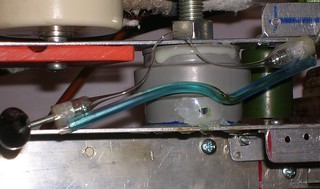
The snapshot of a capillary spark gap in operation is shown on fig 13.
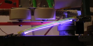
Fig 13. Capillary spark gap in operation. It resembles a flashlamp. Attentive
inspection of the image shows that the spark channel is "double". Since the
single spark can have only one channel this picture proves that there are
really two (or more) sparks and hence two (or more) electric pulses.
12.02.2016
HYDROGEN FILLED SPARK GAP
As it came to the usage of the homemade gas-discharge sealed-off bulb, why
not to fill it with something better than the plain air? E.g. with the hydrogen.
Any literature devoted to gas discharge radio components says that the electron
ion recombination in the hydrogen is faster than in other gases. (There are too
many of references to give a favour to one particular book or article. Lets
consider this as the common knowledge.) This fact is, for exaample, exploited
in those hydrogen thyatrons, they always like to use to pump the copper halide
lasers.
Interlude 4. Chemical one. THE HYDROGEN.
Unlike the neon, helium or even nitrogen, the hydrogen is comparatively easy
to get at home. It is cheap, non-corrosive and non-toxic. Some people stress
the danger of its flammability, but we use the flammable gases (like liquified
butane for our torches) everyday and still alive. With taking the elementary
care and when handling the small amounts, the hydrogen is pretty safe.
At school we are taught that almost any reaction of acid and metal will
produce the desired hydrogen. E.g. one could take a bag of steel nuts and put
them into a bucket of vinegar. Alternatively one could take a clump of
aluminium foil and put it into a jar of hydrochloric acid. The things are less
forgiving in practice however. Some of the reactions are too slow for Your
practical use and others are too fast and uncontrollable.
To provide You a good example of how not to do I'll tell You my own story:
----------------- !!!KIDS DONT DO THIS AT HOME!!! -----------------
To begin with I took a small jar filled to one half with an accumulator
electrolyte (diluted sulfuric acid). I put there some aluminium foil (cut
into pieces) and closed the jar with a lid, equipped with a pipe connected
to an empty balloon. I waited for some time, but there were no bubbles of
hydrogen. The oxide coating of the aluminium prevented the reaction to start.
I opened the jar and added a bit of kitchen salt there to aid the dissolving
process. A minute later there appeared the hydrogen bubbles and everything
seemed to be OK. I closed the jar with the lid and set it aside.
Some time later a noise had attracted my attention. When I reached the jar
the liquid in i was already boiling. It was too late to do something. The
balloon had popped and the bouling liquid began to erupt through the open
pipe. Imagine a fountain of a sulfuric acid and You will get the scale of
the disaster. It made my day... full of cleaning and repetance...
I hope now You have a feeling what I mean by the words that the reaction
goes "too fast".
-----------------------------------------------------------------
Whatever was said in Your textbooks, You practically have to fall to use
of zinc only with hydrochloric or sulfuric acid. The latter is more easy
to obtain since it is sold in automotive stores as the electrolyte for
lead-acid accumulator batteries.
Zinc can be readily obtained from Your common flashlight batteries. Use
only the so called "salt type" batteries. Don't bother to use alkaline ones,
the zinc there has very unsuitable form. Look carefully for the presence of
the "0% mercury, 0% cadmium" sign - we don't want to be poisoned, are we?
(Also don't dismantle rechargeable batteries, lithium batteries, and so
on. Look only for the known types, e.g. "R06", or else the result of the
exhumation may be unpredictable and undesireable.)
Zinc amount in a medium sized salt baterry (e.g. R20 type) is enough to fill
a party balloon.
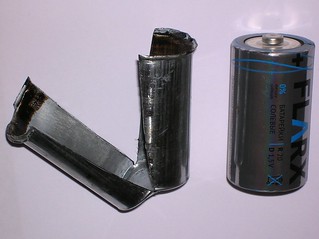
Find a small bottle (150..250 ml ones are good enough). Avoid
using the wide neck vessels, or else it will be hard to seal it tight enough to
endure the pressure, which is needed to fill the balloon. (On the other hand
if You are using some low pressure thing, other than balloon, to gather the
hydrogen, feel free to use wide neck jars.)
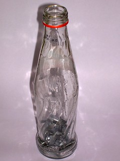
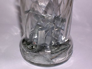
Put 10 - 12 grams of zinc into Your bottle and add 100..150 ml of the
lead-acid batteries electrolyte (which is actually 30% sulfuric acid). Avoid
to leave too much of free space (not occupied by the liquid) in the bottle.
Since the free volume is occupied by air, this air will contaminate Your
hydrogen. It may form a flammable (or even explosive) gas mixture, and it
may interfere with the proper spark gap operation. So it comes that the air
contamination is bad in any case. It is good if Your bottle is small enough
to have 10..50 ml of free volume above the liquid and beneath the lid.
Otherwise add some tap water to the bottle to reduce the free volume. (Too
much dilution makes the reaction to be too slow, so don't use vessels larger
than 330 ml. Too concentrated acid is bad too, because of the zinc sulfate sedimentation, which makes it difficult foe the fresh acid to acess the metal surface.) Another hint to make the reaction to go fast and smooth is to add a very small amount (~100 mg) of copper sulfate into the sulfuric acid. The copper settles on the zinc surface in form of thousands of little spots and makes nano galvanic pairs that improve the reaction.
Then just close the bottle with a lid, having some hose to attach the balloon
to. (It is better if the gas receiving balloon have been attached to the hose
beforehands. It might be too difficult to try to attach it tightly when the
reaction goes on already.)
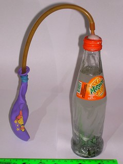
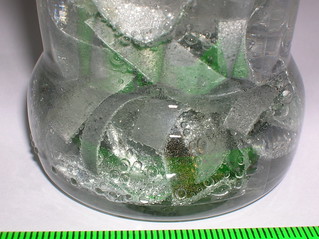
It takes a hour or two for the ballon to enflate. May be it is wiser to
keep an eye on the bottle from time to time during this period.
When the balloon is full, detach it from the hose carefully and use as You
would do with any other gas-containing balloon (e.g. helium filled one.)
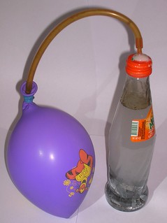
If You took enough care to avoid any air contamination, the ballon is safe
to handle. (If You ignited it, in the worst case, it will pop with a soft
flash of flame.) On the contrary, if You feell like there can be too much of
air inside the balloon, it is better not to use it. Discard the gas safely
and repeat the process from the beginning.
Finally You will end up with a balloon full of hydrogen, that You can use
to fill Your lasers, spark gaps or whatever.
From the very beginning there was an idea not to make a special hydrogen
spark gap, but to fill the existing one (SG3 on fig 1.). I.e. to attach some
hoses to it and to blow through with hydrogen before each laser run. However
the healthy laziness made an advise to look into the literature and see how
people do this and what they get.
As usual each other literature source contains a cue that hydrogen filled
devices can work at higher repetition rates. E.g. in [Marshak I.S. Pulsed
Light Sources. M.: Energiya, 1978] has a reference to another work where the
authors got up to 400 kHz repetition rate using a simple hydrogen lamp (read
as "spark gap") being fed by a simple RC circuit. There is even a note that
the pressure was atmospheric, the spacing was 23 mm and the voltage was 23 kV.
No other data is given (e.g. whether it was a free discharge or a limited by
the glass borders one and so on). The notes that the hydrogen has the recovery
time less by one order of magnitude are present in Handbook on Elements of
Radioelectronic Devices and in Perkin-Elmer's catalogue. However when You
want examples or detailed parameters, You will meet the necessity to use
the abstracts only, or to pay 30 bucks for each article, or even 300 bucks
for a book. And still there can be no usefull information and You have no
other way to check, if there is one, other than to read and pay for this.
It a pity but the scientific publishers do not adopt the "shareware" method
and they are continiously trying to sell You a cat in the bag. Here goes
the Liberty of the Information.
Nevertheless the information, that I was able to get from the numerous
abstracts of articles devoted to hydrogen spark gaps, was enough to make me
afraid of using the direct way (filling the existing ambient pressure spark
gap with the hydrogen gas). I came to the conclusion that the hydrogen alone
may be not enough, and the device should have somewhat reduced pressure and
some kind of tubing having a small diameter.
The device was made in two variants: with the spacing between the electrodes
equal to 30 mm and with the spacing of 40 mm. The bore of the narrow neck of
the galss tubing is about 2 mm in both cases. Refer to figure 14.
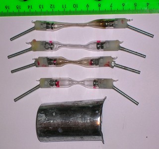
Figure 14. The homemade hydrogen spark gaps. The
new ones is clean. The dirty ones having been in operation for a
while.
The required filling pressure appears to be ~0.5 bar for the model with
30 mm spacing and ~0.35 bar for the one with 40 mm of spacing. I can remind
that the pressure was specially choosen for the hydrogen spark gaps to have
their self triggering voltage equal to the one of the ambient pressure air
filled spark gaps having 5 mm of spacing and round-to-plano type (it is about
13 kV). As it comes out the dielectric strengh of my hydrogen is about one
third of the strength of the ambient air and it differs greatly from the data
given in wikipedia (see the article named "dielectric gases").
The hydrogen filled spark gaps were installed into the laser feeding circuit
shown on figure 15.
                   Cp1
                   470 pf
               +-----||-------+
        Rb0    |              |
  (-)  100k    |              |
   0---/\/\/---+-----I (------+----------+-------------+
               |                         |             |
               |     SG1                 |             |
               |     10 mm               /             /
               |                   Rb2   \             \ Rs2
               |                 45 kOhm /             / 8.3 MOhm
               |                         \             \
               |                         /             /
               |                         |             |
               |                         |             |
               |             Cs2 4nf ||  |             |
               |            +----+---||--+----+        |
               |            |    |   ||  |    |        |
               |            _    |       |    |        |
               |           /o\   / Rs    |    |        |
               |       LT1 | |   \ 5k6  ---   V        |
              ---          |x|   /      ---     HSG    |
              ---          | |   \   Cp3 |    ^        |
               | Cs0       \o/   /   470 |    |        |
        Rb1    | 30 nf      -    |    pf |    |        |
       100k    |            |    |       |    |        |
   0---/\/\/---+------------+----+-------+----+--------+
  (+)
Fig 15. Pulse forming network based on the homemade hydrogen filled spark
gap (HSG) for copper halide homemade laser. SG1 is the round-to-plano ambient
air spark gap having 10 mm of spacing between its electrodes. HSG - hydrogen
filled spark gap (500 mbar, 30 mm of spacing between the electrodes, enclosed
into 6 mm bore glass tubing, which has a "neck" having its bore of ~2 mm). The
circuit requires about 30 kV DC from an external supply.
Both types of hydrogen spark gap (30 mm one nad 40 mm one) have shown good
results with the described above copper chloride laser. The 40 mm model works
noticeaby better, however it may be the statistical spread due to the unequal
attention that was paid for them in the process of their assemblage and
filling. Below are the figures of the hydrogen spark gaps in operation and
video of the laser spot whrn the laser operates at 10 Hz.
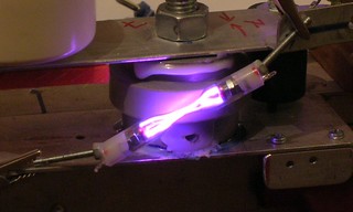
Fig 16. Hydrogen spark gaps in operation. Note the red glow of the spark,
and its typical "branched" shape.
Fig 17. The video of the homemade copper halide laser operating at 10 Hz
with a homemade hydrogen spark gap. The lasing is quite stable. The spark
gap was filled up with hydrogn 3 days ago, sealed off, and still works.
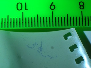
Fig 18. The traces of the homemade copper laser beam on the undeveloped
photomaterial. The beam was focused with a lense having FL=25 mm.
Usage of a rather powerfull (400W x 30 kV rated) power supply has allowed to
achieve the repetition rate of 10 Hz. With this repetition rate it was almost
possible to measure the beam power. It appeared to be 2 mW (+- a value of the
same order with the measured one). The measurements are being impeded by the fact
that calorimeter does react to the heater's radiation. Even when it is placed
more that 1 meter away from the laser.
The hydrogen spark gap does heat up. But much less than its air filled
analogue. After a pair of minutes of operation at 10 Hz it is just hot to touch.
However the cathode sputtering goes fast and limits the lifetime of the spark
gap.
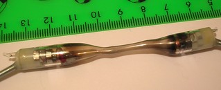
Good news are that the metal layer on the surface of the glass tubing looks
shiny. It means that in the process of making homemade mirrors by the cathode
sputtering one may reduce to usage of the hydrogen and hence avoid the use
of the expensive rare gases.
IN SEARCH OF POWER. ON THE WAY TO A POWERFULL BUT STILL AFFRORDABLE
POWER SUPPLY UNIT
As it is seen above, my most powerfull power supply unit was able to drive
the laser only up to 10 Hz. The laser yields about 2 mW and about 100 mcJ.
So far it looses a bit to my nitrogen laser pumped dye lasers and cosiderably
gives up to my flashlamp pumped dye lasers both in the average power and in
the energy per pulse. The complexity of the devices is not to compare at all.
The copper vapour lasers are said to be hard to be scaled towards more energy
in the pulse, but easy to be scaled towards the higher repetition rated.
However here I meet the necessity to use a much more powerfull power supply.
As they say: "I need more power!" But where to get it? High voltage
transformers are still not lying on the road. And to wind one is so boring
thing that I will try to avoid it at any cost. What's then? Microwave oven
transformers? Ignition coils with dimmers? Or refurbishing an arc welder? I
decided to start from a second variant.
I had got two ignition coils from an old fashioned car and started to
torture them. The test circuit is shown on figure 19.
  o------+---------+
         |         |
         |         /
         /         \
         \      Rb /
      Ri /         \           +-----+-----+
         \         /     Cs1   |     |     |
         /  SW1    |   ||      (     |     |
         |         +---||----+ (     | Cs2 |
         +--- ---  |   ||    | (    ---    V
         |   T   \ V         )H(    ---      SG1
        ---       ---        )H(     |     ^
      Ci---        | SCR1    )H(     |     |
         |         |         | |     |     |
  o------+---------+---------+-+-----+-----+
Figure 19. Test circuit for the ignition coils.
The ultimate task for the coils was to be able to charge my Maxwell capacitor
(30 nF) up to 26 kV (10 mm of spacing in SG1 on fig 19.) in order to be able
to drive my existing laser pumping circuit. In order to get at least 50 Hz
repetition rate the coils should be able to charge the storage capacitor in
one pulse. Otherwise I would fall back to the use of direct current and
transistors in place of thyristor SCR1 and get no excess of power. The test
circuit was fed by 300 V DC directly from a diode bridge connected to 220v
mains.
The coils failed to fullfill their ultimate task (to charge 30 nf up to 26 kV
in one pulse) either being used alone, or in different connections to each
other (parallel connection of the coils, antiparallel connection of their
primaries and series connection of their secondaries and so on).
The top result I got was to charge 14 nf up to 21 kV (8 mm of spacing in SG1
on fig 19.) The best connection do do this job was just the full parallel
connection. I.e. their primaries are parallel to each other and their
secondaries are parallel to each other. The storage capacitor needed do this
job, appeared to be a 1000 mcf electrolytic one.
50Hz*1000mcf*300V^2/2=2250W. - Sounds not good.
By the way there's probably no need to charge the full Maxwell of electricity.
Because it gathers about 10 joules while the capacitor that does really feed the
laser (Cs2 on Fig 15) gets only 338 mj (double this for both dissociation and
pumping pulses).
The test circuit was then modified to represent the real situation more
closely (see fig 20.)
  o------+---------+
         |         |
         |         /                    Cs2
         /         \                          +----+
         \      Rb /                    ||    |    |
      Ri /         \           +-----+--||----+    |
         \         /     Cs1   |     |  ||    |    -
         /  SW1    |   ||      (     |        |   /o\
         |         +---||----+ (     |        /   | |
         +--- ---  |   ||    | (     V        \   |x| FL1
         |   T   \ V         )H(       HSG    /   | |
        ---       ---        )H(     ^        \   \o/
      Ci---        | SCR1    )H(     |      1k/    -
         |         |         | |     |        |    |
  o------+---------+---------+-+-----+--------+----+
Figure 20. The advanced test circuit for the ignition coils.
FL1 - is a photographic flash lamp. Used here to emulate the real load.
Also usefull for the remote measurements.
In the new test circuit the secondary storage Cs2 was choosen to be 4 nf,
the spark gap was changed to the hydrogen filled spark gap, like the one used
before to drive up the laser, and the circuit was loaded onto a flashlamp.
The flashlamp is very usefull to indicate how the circuit behaves. Just use
a photodiode and oscilloscope and see how many flashes this circuit gives.
Since the frequencies are low here (100 mcs corresponds to only 10 kHz) You
may even use the audio card of Your computer to do the measurements (google
search for the winscope program). And Your oscilloscope/computer is safe here,
because there is only optical connection.
The typical oscillograms of the pulses given by the circuit under
consideration are given on figure 21.

Figure 21. The typical oscilloscope traces of the light pulses, produced
by the flashlamp FL1 on figure 20. One can see that there definitely are
two (or more) pulses and the time spacing between them is about 100 mcs.
As one can see, the circuit really produces several light pulses per one
ignition. And the parameters of the pulses are good enough to pump the copper
vapour laser. However the second pulse begins to appear only when the primary
storage is about 750 mcf.
So the conclusion is that if You have no high voltage power supply unit the
circuit using a thyristor and two ignition coils like the one shown above is
simple enough and suitable to feed the copper vapour laser (just replace the
SW1 switch by a diac to access the autofire function). However If You want
a high repetition rate this circuit has too low efficiency to fit Your needs.
For most of You the information given above is enough to design a power
supply for a DIY copper laser based on the ignition coils. However for those
lazy ones I bothered to draw up the full schematics, refer to fig 22.
 o-------+
~220     | Diode Bridge
         + (e.g. KBU1006)
        / \
       /   \
    +-+ |>| +---+-----------+
    |  \   /    |           |
    |   \ /     /           /
    |    +      \           \ Rs2*
    |    |   Rt /<-+        / 100 ohm
~220|    |   2M \  |        \
 o--)----+      /  |        /      Cs1 1000 microfarads
    |           |  |        |   +||
    |           +--+   +----+----||-----+                       Cs2
    |           |      |         ||     |                       4 nF
    |           /      |                +------+   Rc1 0..50k       +---+
    |       Rs1 \      |  SCR1          |      |                ||  |   |
    |       10K /      +--|>|----+      | +----)-+--/\/\/----+--||--+   |
    |           \            \   |      | |    | |           |  ||  |   -
    |           /             |  |      | |    | |           |      |  /o\
    |           |             |  |      | (    | (           |      /  | | las.
    |           +---|><|------+  |      | (    | (           V  Rc2 \  | | tube
    |           |    Diac        |      )H(    )H(       FSG     1k /  | |
    |     Ct   ---   DB3(DB6)    | IgC1 )H(    )H( IgC2      ^      \  \o/
    |    200nF ---               |      )H(    )H(           |      /   -
    |           |                |      | |    | |           |      |   |
    +-----------+----------------+------+-+----+-+-----------+------+---+
Figure 22. Full circuit of powering a homemade copper halide laser directly
from 220V AC mains. Primary storage Cs1 is electrolytic 1000 uF capacitor.
Its negative side should be towards the coils and its positive side should
be towards the positive poer supply from the diode bridge. IgC1 and IgC2 -
a pair of (old fashioned) ignition coils connected in parallel to each other.
Don't use modern type ignition coils, since they're designed for low primary
voltages and would burn here. FSG - some kind of high repetition rate spark gap,
having 13 kv self triggering voltage. It may be a hydrogen filled spark gap or
a salt filled spark gap (both described above). Rc1 - Time correction resistor.
Use if the delay between pulses is too short. Usually the active resistance of
secondaries of the coils does the work and there's no need to use a separate
resistor. SCR1 - any kind of very powerfull (very BIG) thyristor. Diac
may be of almost any type (DB3, DB4, DB6, etc) however You may need to adjust
the value of the timing resistor (the pot Rt).
I've never tried to use it on a real laser (since I have better solutions)
but its vital elements have been assembled and tested (see above) so I'm pretty
sure that it will operate successfully. Note the absence of the high voltage
primary storage (Maxwell). Its functions are taken by a low voltage Cs1 here.
The circuit should be applicable for the bursts repetition rates up to 10 Hz.
You may need to choose a better value of the safety charge resistor Rs2, though.
R2 should be VERY POWERFULL (a lamp or a boiler heater).
20-23.02.2016
STRAFE RIGHT, STRAFE LEFT
When trying to increase the repetition rate, each watt of power makes the
difference. So it was needed to ensure, that in the circuits under
consideration the pumping energy is just enough for the laser to work good
and makes no excess. In order to ensure this, some tests were made.
The laser was fed by the circuit, shown on fig 15. The spark gap had 40 mm of
spacing between its electrodes and was filled with hydrogen at about 1/4..1/3
of atmospheric pressure (its triggering voltage was 13 kV). (A hint: if Your
hydrogen spark gap requires too low pressure for the 13 kV of triggering
voltage it means it contains too much of contaminations and should be refilled.)
The laser tube had already been in use for some time, but still lased good.
The tests started from obtaining more or less stable lasing without any
changes in comparison to the previous runs (fig 15).
Then the capacity of the secondary storage (CS2 on fig 15) was reduced from
4 nf to 2 nf (one of two Murata's disconnected). The laser appeared to be still
operational, but the brightness of its spot was noticeably lower. It looked
like the laser wants more energy... or the time constant had shifted into the
region bad for the operation. To return the time constant to its place, the
time control resistor (Rb2 on fig 15) was increased from 45 kOhm to 90 kOhm
(one of two parallel 90 kOhm resistors was removed). The spot became even less
bright and laser began to miss pulses. It means that the output decreases
with decreasement of the storage capacity not due to the shift of the time
constant. And since Rb2 controls only the charging time of Cs2 (and this time
has changed from 45e3*2e-9=90 mcsec to 90e3*2e-9=180 mcsec) it means that
200 mcsec time constant is a bit too much for this laser.
Then the Cs2 was set to 4 nf again and the Rb2 was left at 90 kOhm (time
constant is about 400 mcs). The lasing did vanish... Carefull scan of the
buffer gas pressure and tube temperature gave a bit of success - one or two
times the laser spot did appear, but thats all.
Return of Cs2 and Rb2 to their nominal values (4 nF and 45 kOhm) produced a
rather stable lasing (as it was before these tests), so one can estate that
the laser is still alive and the changes of output were exactly due to changes
of Cs2 and Rb2.
The preliminary conclusion, I came to, was the next:
- The energy in the secondary storage (4nf @ 13 kv) is just enough for the
laser to lase properly and it is a bad idea to reduce either the capacity or
the voltage. On the contrary the laser would be pleased if the capacity or
the voltage was higher.
- The choosen time constant (200 mcsec) is a bit too high for the optimal
performance.
A note on the variation of the parameters: If You have got a 30 kv rated
100 kOhm pot or a RF variable capacttor rated to 4 nf 30 kV - good for You.
And I am limited to the use what I have: I do the capacity variation by adding
the capacitor or removing the capacitor. And the resistance likewise - add
resistor/remove resistor. So the steps are quite rude, and I can easily miss
the real optimum. However I hope that the general tendencies are caught well.
A shopping tour to radio-market has brought a result having the form of
two large old fashioned wirewound resistors. They are rated to 50 W 36 kOhm
each and look like they can endure more than 50 kV.
One of them was put in place of Rb2 (fig 15) and the laser got a test run.
The performance difference (in comparison with the situation, when 45 kOhm
is set there) is barely measurable, but visually the laser behaves better
than it did before.
Another run with two parallel 36 kOhm in place of Rb2 (means 18 kOhm total).
The spot became even brighter, but... the performance began to degrade from
pulse to pulse in long series. However the first pulses in the series became
so powerfull that it was almost easy to get a dye lasing almost at will. See
the figure 23. Despite the fact that the ouptput degrades in long series, the
initial pulses are powerfull enough.
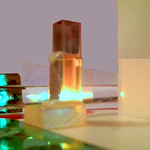
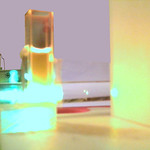
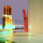
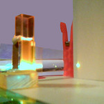
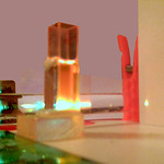

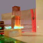
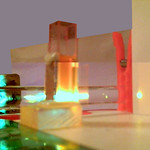
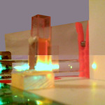
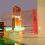
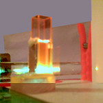
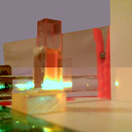
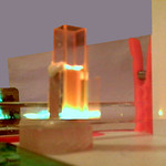
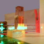


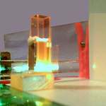
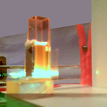
Figure 23. Some shots of dye lasing under the beam of DIY copper halide vapour
laser. With the reduction of the pulse-to pulse delay in the burst the energy in
each pulse has risen to the level, where it is almost easy to pump a dye
cuvette whenever You want.
THE INDUCTIVITY OF THE PUMPING CIRCUIT
Another thing I always wanted to check out since I got the information about
the lifetime of the copper atom upper laser level( being equal up to 500 ns),
was the real requirement to the pumping pulse duration. The 0.5 mcs of the
lifetime are close enough to the lifetime of CO2 upper level in TEA laser
conditions. So the requirements for the speed of pumping ought to be similar
(with a discount for much lower feeding currents) and all those mumblings about
50 ns, needed to feed the copper laser, sound like kidding.
The simpliest way to prolong the pumping pulse in the circuit being tested
is to include the inductivity in series with the laser tube (see fig 24.)
                   Cp1
                   470 pf
               +-----||-------+
        Rb0    |              |
  (-)  100k    |              |
   0---/\/\/---+-----I (------+----------+-------------+
               |                         |             |
               |     SG1                 |             |
               |     10 mm               /             /
               |                   Rb2   \             \ Rs2
               |                 45 kOhm /             / 8.3 MOhm
               |                         \             \
               |                         /             /
               |                         |             |
               |                         |             |
               |             Cs2 4nf ||  |             |
               |            +----+---||--+----+        |
               |            |    |   ||  |    |        |
               |            _    |       |    |        |
               |           /o\   / Rs    |    |        |
               |       LT1 | |   \ 5k6  ---   V        |
              ---          |x|   /      ---     HSG    |
              ---          | |   \   Cp3 |    ^        |
               | Cs0       \o/   /   470 |    |        |
               | 30 nf      -    |    pf |    |        |
               |            |    |       |    |        |
               |            )    |       |    |        |
               |         Lt )    |       |    |        |
               |            )    |       |    |        |
       Rb1     |            |    |       |    |        |
       100k    |            |    |       |    |        |
   0---/\/\/---+------------+----+-------+----+--------+
  (+)
Figure 24. The circuit for DIY copper halide laser pumping, used for the
tests directed to finding out how long the electric pumping pulses can be.
The circuit coincides the one shown on the fig 15, with the only difference
that test inductor Lt is connected in series with the laser tube LT1.
The results are following
| Lt type |
effect |
| 30 cm of copper wire with diameter of 1 mm |
stable lasing, no visual output drop |
| 70 cm of copper wire with diameter of 1 mm |
stable lasing, barely noticeable visually drop of output power |
| 4 turns of copper wire with diameter of 1 mm on a cut of 2 inch plastic tubing |
stable lasing, visually prominent drop of output power |
| 30 turns of copper wire with diameter of 1 mm on a cut of 30 mm paper tubing |
unstable lasing, nearly the threshold, the spot isn't bright and appears rarely; operational only in narrow range of tube temperatures and buffer gas pressures |
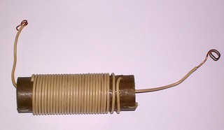
Using a well known formula from a general physics course we can estimate
the inductance of coil as
Lt=uo*n^2*s/l
where uo=4*pi*1e-7 H/m - magnetic permeability of void,
n - number of turns
s = pi*r^2 - coil core cross section
l - length of the winding.
r - radius of the turns
The used coil was 30 mm in diameter and 60 mm long. Therefore
s = pi*r^2 = 7.07e-4 sq.m.
Lt=4*pi*1e-7*30^2*7.07e-4/0.06=13.3 uH
The period of LC tank oscillations is Tlc=2*pi*sqrt(Lt*Cs2)=1.44 mcs
And the duration of the electric current pulse will be equal to the first
half period, i.e. tau = 720 ns. In reality the electric pumping pulse
is even longer, because it is prolonged also by the active resistance of the
laser tube.
For my laser in the given conditions prolongation of the pumping pulse to
720 ns brings the laser to its threshold. In other conditions (e.g. when
feeding voltage is higher) the allowed pulse duration may be even longer.
Several hints that were not stressed enough above
As it was found out (thanks to the e-mail feedback) some important moments
were either missed in this report or were not explicit enough. Here is a good
place to point them out.
- It was said above that the measured power was about 2 mW at the repetition
rate of 10 Hz. And newertheless I continue to estimate the output energy
per pulse by the value of 100 mcJ. Isn't it astonishing?
Naturally the pulse forming networks shown on figures 7, 15, 22, 24 do not
obey to produce exactly two pulses per each firing. On the contrary in most
cases thy produce three or (more rarely) four electric pulses per one burst.
Assuming that the first pulse in burst goes for dissociation, we get that
each firing of the leader spark gap causes 2..3 pulses with lasing. For the
10 Hz of the repetition rate it gives 20..30 laser pulses per second. Thus
it means that their energy is 2mW/20..30[1/sec]=67..100.. mcJ. And if one
wants to calculate how much power the tube would give if it was driven at,
say, 10 kHz of repetition rate, it is important to take into account that
one can not send pairs or triples of pulses at this rate. It means that the
output will be only 0.67..1 W and not full 2 watts of power as one might
think. And even those 0.67..1 watts will be achieved only if the dependence
of power to the repetition rate is linear, but in reality it happens so very
rarely.
- When one tries to make some conclusions based upon my shared videos (e.g.
conclusions on the dependence of the output power and stability to the
pulse forming network schematics), the one should take into account the
growing skills of the author to maintain the proper temperature and pressure.
E.G. I succeeded to learn to cut the gas flow just in time to get the proper
pressure for lasing even with the existing inertia of the vacuum system and
with the correction to the ambient pressure (my vacuummeter shows the
relative pressure, not the absolute one). Here is a good place to note that
the pressure does also depend to the temperature of the gas in the tube.
However for the laser only the concentration of the buffer gas particles is
important, not the pressure itself. That's why choose some reference
temperature and measure the pressure only at this temperature. For example
in this web report all the pressures are given for the cold tube (room
temperature was 25 Celcium degrees).
- Yet another thing, one should take into account, when trying to predict how
the tube would behave at high repetition rates (meaning several kilohertz
and the self heating mode in the first order) is the short-term degradation.
Here the long term degradation means the decreasement of the laser output
due to the copper halides exhaustion, due to the translucent coating of
the tube windows and due to the shunt action of the copper layer being
accumulated on the walls of the tube. The later design of my tubes show the
lifetime of 6..10 hours for this kind of degradation. The "later" tubes
differ from the "older" ones mainly by the increased load (up to 10 grams)
of copper monochloride and by using the comparatively long electrodes, that
provide the distance between the windows and the discharge zone not less
than 100 mm.
The short-term degradation is the thing that happens to the tube, when
You've adjusted the temperature and pressure to the optimal values, when
you've obtained a stable lasing and cut the gas flow in the vacuum system.
In the gas static mode the output power decrease nearly by one half per
each thousand of the generated pulses. Buffer gas exchange (with some pause
for the copper monochloride to have some time to vaporize enough) the
output power returns back. This is not due the leaks, since the tube, being
turned off) is capable to keep the conditions needed to produce the initial
power for mor than one hour. This is not overheating, because the output
power does not want to come back without buffer gas exchanging.
Most probably the short-term degradation is due to the chlorine or even
iodine accumulation (I try to choose the kitchen salt not marked as
iodinated for my experiments, but even though it if far from being of
perfect chemical purity).
If we assume that the rate of the short-term degradation will be kept
at its present level when going to higher repetition rates (it may, or may
not be true) then at 10 kHz our laser will continue to lase only for less
than a second. And to awoid this one should apply the gas flowing mode.
The difficulty here is that the gas flowing speed must be high enough to
carry out the detrimental impurities, but on the other hand it must be
slow enogh to allow the needed quantity of the copper halide to vaporize
and stay in the discharge zone.
- Another unusual phenomena that can be observed when working with copper
halide laser is the "self-vacuuming" of the tube. For example, one day
You'd used Your laser, cut off the valves, and left it to stay overnight
with a pressure of one inch of Hg. Next morning You feel astonished when
finding the tube staying at pressure less than 1 torr. And moreover the
tube demonstrated leakage of about 1 inch Hg per day when it was just
assembled.
Since I don't believe in "self-curing" of the leakages, this most probably
means that the baked cuprous chloride powder is a good gas absorber, or
even getter. The implicit prove of this it that the phenomena was never
observed for the tubes containing no cuprous halide.
The practical conclusion is that all the leakages of the tube have to be
found BEFORE loading of the tube. After the loading the leaking tube can
mimic the ideal one for a long time.
- It is common to assume that the tempaerature range of normal laser operation
depends mostly (if not only) to the type of the copper salt used in the
laser. However the experience tends to correct this habit. The temperatue of
lasing depends stronly to... the feeding pulse parameters. Basing upon the
results of the work [Weaver L., Liu, C.S., Sucov, E.W., Superradiant emission
at 5106, 5700, and 5782 A in pulsed copper iodide discharges. Quantum
Electronics, IEEE Journal V:10, Iss:2, pp:140-147] (i have an access to its
abstract only, its full text is unavailable for me) the lifetime of the
upper laser level depends stronly to the density of the copper atoms, and it
varies from 10 ns for low densities to as much as 400 ns for the high ones.
It means that fastest systems (low inductive and low resistive) can operate
at the lowest temperatures, and more slow systems require more heat. However
the practice (e.g. tests with the additional induction coil, etc) teachs
that usually the temperature range primary dependency refers not to the
inductance. but mostly to the design of the spark gaps and to the quality
of their firing (astonishing that it depends not only to the fast discharge
spark gap (HSG on fig 24) but on the leading one too (SG1 on fig 24). Most
probably it affects the delay between the pumping pulses in the burst,
however i haven't yet researched this question in details.
The next important factor is the quality and freshness of the copper halide
layer on the walls of the laser tube.
And the correspondent temperature variations have values of several tenth of
degrees (not several degrees as one might expect), which can yeld up to one
hundreed of degrees in total, whwn all factors act towards one side.
I.e. the operation temperature is not some 'physical constant', but rather
than that it is just a 'design parameter'.
- A pair of words on the hydrogen filled spark gap. As one can see on the
videos the hydrogen spark gap gives very good results, and it may look like
any kind of spark gap needs only to be filled with hydrogen to make the
copper halide laser happy. It is not quite correct.
Generally when the delay between the pulses in the burst is large (e.g.
when Rb2>40 kOhm, fig 15) the laser agrees to operate with most hydrogen
filled spark gaps, that You can make. However the performance is not high.
When You try to increase the performance by making the delay low, not all
of the hydrogen spark gap perform well. I decided to make the description
of a good one, but rather than put it here, I will add it to the guide
devoted to all kinds of spark gaps. So wait a bit and it will appear there.
TRIPLE REPETITION RATE FOR FREE (Or NOT AT ALL?).
Lets look at fig 15 (or fig 23 it is closer to this place of text). And lets
see what happens when the secondary storage charges and discharges.
The electric charge needed to charge the Cs2 to 13 kV is 4nf*13kV = 52 uCl.
And when this charge goes from Cs0 to Cs2, the resulting voltage on Cs0
becomes 26kv- 52uCl/30nF = 24.27 kV.
The dissipated enegry is (30nF/2)(26kV^2-24.27kv^2) = 1.3 J. However the
secondary storage has got only 4nF*13kv^2/2 = 0.338 J up to this time. The
other energy has just gone to heating the resistors. So it looks attractive to
reduce the intrinsic energy loss of the feeding circuit. Practically it can be
achieved by using an inductor in place of the ballast resistor(s) Rb2 (fig 15).
See figure 25 below.
                   Cp1
                   470 pf
               +-----||-------+
        Rb0    |              |
  (-)  100k    |              |
   0---/\/\/---+-----I (------+----------+------------------+
               |                         |                  |
               |     SG1                 |                  |
               |     5 mm                |                  /
               |                   Lb    )                  \ Rs2
               |                 0.68 H  )                  / 8.3 MOhm
               |                 x30 kV  )                  \
               |                         )                  /
               |                         |                  |
               |                         |                  |
               |             Cs2 4nf ||  |                  |
               |            +----+---||--+----+             |
               |            |    |   ||  |    |             |
               |            _    |       |    |             |
               |           /o\   / Rs    |    |             |
               |       LT1 | |   \ 5k6  ---   V             |
              ---          |x|   /      ---     HSG         |
              ---          | |   \   Cp3 |    ^ 13 kV       |
               | Cs0       \o/   /   470 |    | ~5 eff.mm   |
        Rb1    | 30 nf      -    |    pf |    |             |
       100k    |            |    |       |    |             |
   0---/\/\/---+------------+----+-------+----+-------------+
  (+)
Fig 25. Pulse forming network based for the DIY copper halides laser with
the reduced losses. The hydrogen filled spark gap (HSG) has its spacing and
pressure being specially choosen to provide 13 kV of self triggering voltage
(it is equivalent to an ambient air filled spark gap with 5 mm spacing).
Lb - ballast choke. Note that the inductive ballast diminishes the requirements
to the intitial voltage - the spacing in SG1 is set to 5 mm, and not to 10 mm
as it was before.
The job looks rather simple, however the necessary inductance is quite large.
Calculations show that it should have its value of about 1 Henry. Multiply this
by the fact that it have to endure the voltages up to 30 kV.
Quick tests with different cores (ferrite toroids, iron E-cuttings, and many
other) have shown that 100 turns of wire yield only about 1 mH and barely
depend to the core material and winding style. The "N1^2/N2^2"-like scaling
immediately shows that the full (1 H) sized winding has to contain not less
than 3000 turns. And it sounds bad, because there's no other way to make the
coil to endure the necessary voltages other than making its winding smooth and
regular, and providing very good insulation between its turns and layers.
I've got a coil from some relay device with its mark paper saying that it had
6800 turns of 0.15 mm wire. Its measured inductance appeared to be 0.58 H
without any ferrite core. Its main drawback was that it had a low voltage
design. I.e. without any dielectric film between its winding layers and without
any grouting with wax or anything else. One might expect that at the necessary
voltages the coil would be full of breakdowns and flashovers. But the
perspective of winding one by hands looked even more discouraging. So nothing
else was left other than to try to make some kind of impregnation.
I took a jar of car engine oil, put the coil there and connected the jar to
my vacuum pump. At first there appeared much of foam, but my safety bottle
took it all. (Generally it is a bad idea to connect Your vacuum pump directly
to Your lasers or other systems. Usually people use vapour traps being cooled
by liquid nitrogen, but even if You have no liquid nitrogen it is better to
use some buffer reservoir, letting solid particles and liquid drops to stay
in it without getting into the pump. In the simpliest case it may be some jar
with its lid being equipped with two hoses far enough from each other. This
solution will prolong the lifetime of Your pump greatly.) I made several cycles
of evacuation of the coil in the oil to the lowest possible pressure
alternating with letting the air in. The idea was to make the oil to move to
the space between the turns. I had no means to control how the process go, so
after a few cycles I installed the jar with the coil into the laser feeding
circuit and gave it a try.
Not only the laser agreed to lase, but it did it when the spacing in the
leading spark gap (SG1) was set to 5 mm, meaning the primary voltage to be
EQUAL to the secondary voltage (controlled by HSG, see fig 25). I used my
low power high voltage supply (approximately 50W rated) that was previously
able to drive the circuit at 2 Hz repetition rate only. With the current
SG1 setting the circuit gave 6 Hz repetition rate. 3 times greater and without
using any additional power!
And just when I started to dream about 30 Hz of repetition rate with the use
of my 400 W rated high voltage power supply, my dreams were broken by some
crackling sound going from the inside the jar with oil and coil. This was the
end. The coil worked just enough to feel how goot it would be to use it.
The good thing is not only that it increases the efficiency and allows to
rise the repetition rate. Even better that it allows to reduce the supply
voltage and gives the hope, that with some tweaks one can use just common
microwave oven transformers (MOTs) to feed this power hungry thing.
Indeed, single MOT yields 2.4 kV RMS, giving 3.4 kV amplitude (and DC after
rectifier too). Thus two MOTs will provide 6.77 kV and further on this can be
doubled either over a voltage doubler rectifier or by resonance charrging of
the primary storage capacitor. Both ways will leave us with 13.5 kV, the latter
one will require yet another high voltage large inductor, though. Since MOTs
are very affordable now, this sounds like an easy way to get the notorious
100 Hz of the repetition rate.
2-5.03.2016
BACKSTEP: THE EXTERNAL TRIGGERED SPARK GAP
The previous tests have shown that the shorter the delay between pulses is,
the more energy per pulse outputs from the laser. Enshortening the delay from
200 mcs to 100 mcs almost doubles the energy. Further decreasement however has
met an obstacle in form of hydrogen spark gaps instability. I.e. most of my
homemade hydrogen spark gaps perform well when the delay is about 200 mcs. Not
each of them appears to maintain the stable operation when the delay is 100 mcs.
And most of them fail when the delay is 80 mcs or less. (The shortest delay I
used with my gaps was 77 mcs). Here the laser begins to skip pulses or even
completely fails to lase, so despite the fact that occasionally it gives very
bright spots its overall performance decreases.
For the time I appeared to be unable to elaborate any other way to make so
short delays rather than to use the "classic" approach utilizing a controllable
spark gap. The schematics is shown on figure 26. And the design of the external
triggered spark gap is shown on fig 27.
  (+)
   0---------------------------+--------------------------------+
                               |                                |
                               |                                |
                               /                                /
                               \ Rb1                      Rb2   \
                               / 91 kOhm                91 kOhm /
                               \                                \
                               /                                /
                               | Cs1                     Cs2    |
           VD1        Css1     | 4.7nf                   4nf    |
                  || 4.7nf     |  ||                        ||  |
         +-|>|--+-||------+----+--||--+      +----+-----+---||--+----+
         |      | ||      |    |  ||  |      |    |     |   ||  |    |
         |      |     SG1 |    |      |  Lb  )    _     |       |    |
         |      /    5.5mm|    |      | 13uH )   /o\    / Rs1   |    |
         |      \         U   ---     |      )   | |    \ 5k6  ---   |
         |      / Rs2         ---     |      |   |x|    /      ---   U SG2
         |      \ 1k1     -    | Cp1  +------+   | |    \   Cp2 |   _ _  9 mm
         |      /         |    | 470             \o/    /   470 |  / ^
         |      |         |    | pf               -     |    pf |  | |
         |      |         |    |                  | LT1 |       |  | |
   0-----)------+---------+----+----------+-------+-----+-------+--+ |
  (-)    |                |               |             |            |
         |                |               |             /            |
         |         Css2   |          Css3 |             \ Rs3        |
         |        3300pf ---         2nf ---            /  8.3 MOhm  |
         |               ---    Rt       ---            \            |
         |  VD2..VDn      |   400kOhm     |             /            |
         |                |               |             |            |
         +--|<|--|<|------+--/\/\/--------+-------------+------------+
Fig 26. Double pulse forming circuit for the DIY copper halide laser
based upon a controllable homemade spark gap (SG2). Cs1 - K15-4 doorknob
capacitor rated to 4.7 nf x 12 kV; Css1 - same as Cs1. Cs2 - 2 x Murata
high voltage (doorknob) capacitors rated to 2 nf x 40 kv. Css2 - KVI-3
high voltage (doorknob) capacitors rated to 3.3 nf x 10 kv. Css3 - K73-13
(mylar rolled) small sized capacitor (2nf x 10 kV). Peakers Cp1 and Cp2
may be any low ESL/low ESR ceramic capacitors (read as "doorknob" ones)
capable for not less than 20 kv. SG1 - a self-triggering spark gap of
the "round-to-plane" type, filled with an ambient air. SG2 - an external
triggered (controllable) spark gap of same design as SG1, but equipped
with an additional triggering electrode. Lb - 30 turns of 1 mm wire along
the length of 60 mm on a paper cylinder having its diameter of 30 mm.
Diodes VD1..VD3 a stack of high voltage diodes just enough to endure
30 kv of back voltage and 1 amp of forward current. E.g. use 15 pcs of
R2000 or EM518 in series here.

Fig 27. The design of the controllable homemade spark gap.
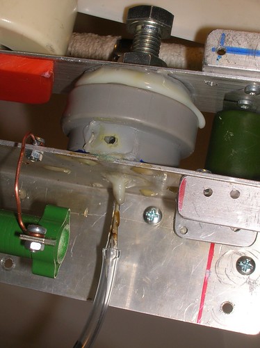
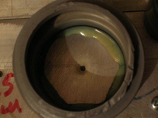
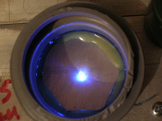
The circuit is rather complicated already, but it still can be expressed
by the humble means of the ASCII grafics. It requires noticeably more high
voltage electronic parts than the circuit from fig 1 does, but still it
sould be in the limits of average HV DIYer capabilities. It also has some
narrow places. I.e. the discharge speed of Css2-Rt-Css3-Rs3 does promise the
unstable work at repetition rates higher than 20 Hz. And it is rather hard
to make the time constant of this circuit lower, together with keeping its
output voltage high enough to trigger the SG2, and with the ability to make
the delays up to at least 80 mcs. And the the most main drawback of this
circuit is that it requires... TUNING. It won't work when just assembled.
You will need to match the Rs2, Rs3, Rt resistors and maybe to adjust
capacities of the Css1..Css3. I can not say this is a hard job, but one must
have a clear understanding of "what affects what" in this circuit. And and
it is uneasy task to give the exhaustive explanation just in a few pages (few
tens of them sound more reasonably).
The alternative way is to use logic chips (integrated circuits - IC's) to
set the delay and some powerfull IGBT's with some ignition transformers to
make the triggering pulse. However if You're using an external clock. not
synchronized to the voltage rising at the storage capacities (Cs1, Cs2) it
would try to fire the circuit when it is far from being ready. On the other
hand if Yor try to trigger Your clock by a high voltage signal (e.g. by SG1
firing), You will meet a delicate problem of making those weak semiconductors
to survive in the conditions of continious high voltage leaks, breakdowns and
flashovers. And don't forget the electromagnetic shock pulse.
Anyways the circuit was assembled and tested. It took not a much of efforts
to upgrade the uncontrollable SG3 from fig 1 to become an external triggered
SG2 from fig 26. It was needed just to drill a hole, to glue a glass capillary
there and to insert a steel wire into the bore of the capillary. When You have
a working laser it's much easier to upgrade it rather than build a complicated
thing from scratch.
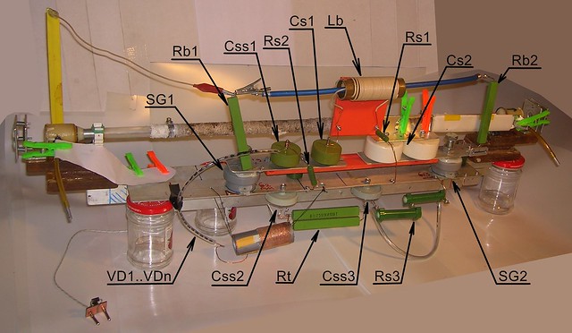
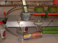
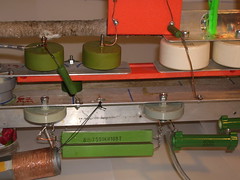
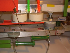
The tuning was rather tricky. The circuit worked good at
low delays between pulses (~20 mcs), but I was not ready to begin with so short
delays, i wanted something more close to the values at which the laser had
worked already. And when i tried to increase the delay (by increasing Rt) the
output signal tend to drop down below the SG2 triggering threshold. The values
of parts, i came to, are shown on fig 26 and correspond to ~80 mcsec of the
delay.
It is really helpfull to be not blind completely when tuning this scheme.
To help Yourself, install a small photo flashlamp in place of the laser tube
(LT1 on fig 26) and use a photodiode with an oscilloscope to see the delay
between pulses (the computer's sound card and the winscope software may or may
not suit - depends to the sondcard). Also it is good to make some transparent
windows in the bodies of SG1 and SG2, to see whether they are triggering or not.
When after the twisted procedure of tuning I'd finally got the 80 mcs of
delay, i let it a test run with my laser. The result is shown on the video
below. The repetition rate was 8 Hz with my ~40W power supply.
Fig 28. Video of the homemade CuHal vapour laser working with the external
triggered spark gap. One can see how the power rises when the temperature
approaches the optimum and diminishes when the laser is overheated or
overcooled. The laser operates in gas-static mode, so the variations of the
pressure are minimal.
The camera steals the difference between the brightness of the spot, seen
by the naked eye. So You can not compare this video with the one, where a
hydrogen spark gap was used. So i need to say explicitly, that the visible
brighness of the spots is lower than one with the hydrogen discharger. And
the average power is below measurements. (Maybe due to the fact that the
circuit with hydrogen spark gap produces bursts containing 2..3 pulses each.)
However the lasing is rather stable, giving up only to the case with the said
hydrogen spark gap.
The next step was to diminish the delay between the first and the second
pulses. It can be done by reducing the resistance of Rt on fig 26. Laser
appeared to be fairly operational when Rt was as low as 50 kOhm. The best
results were when Rt was 100..150 kOhm however. In the preliminary tests
with the flashlamp in place of the laser tube, 50 kohm corresponded to the
delay of 37 mcs, and 100 kohm - to ~70 mcs. Shorter delays reduce the timing
circuit discharge time and thus allow the usage of higher repetition rates.
Finally it was decided to give a try to a more powerful high voltage supply
unit. (As I've written above this one is rated to about 400W.) It gave the
repetition rate at the level of 40 Hz. The lasing was rather stable, almost
without any dropouts. However the percentage of yellow pulses was noticeable.
An attempt to measure the output gave nothing. (I.e. "less than 1 mW").
While I was attempting to measure the power, the stability of the laser
became worse and worse and finally it refused to lase at all. (So I hadn't
enough time to get a video of the laser, operating at 40 Hz. Sorry for that.)
The total time of operation at 40 Hz was a bit less than 5 min.
Further inspection had discovered two weak spots of the circuit. The first
is obviously the stack of diodes. And the second one is the... Css3 capacitor.
It is strange, because the voltages here should be comparatively low and the
capacitor is 10 kV rated. Anyways after it had been replaced by a more reliable
doorknob capacitor the circuit never failed in this place. It was rather hard
to discover this problem: the capacitor behaved like tormal one when tested
with a multimeter, but the ignition signal continued to decrease. And only
after all other parts of the circuit had been checked out, the choice fell
upon this evil-fate capacitor. Most probably it started to leak, but the leak
appeared only at high voltages and could not be discovered with common means.
Another bunch of problems refers to the controllable spark gap itself. From
outside it looks like everything is OK and the spark gap triggers well. But the
laser does not lase. Thanks to the spark gap design, having the movable bolt
electrode, and to the oscilloscope, I've been able to understand what's going
on. First of all at given voltage it has 5 zones of operation
- Self triggering zone. - When the main electrodes are close enough to each
other, the spark gap ignites itself without waiting for any pulse on the
triggering electrode.
- Reliable triggering zone with small and stable delay. - When the main
electrodes are far enough to stop the self triggering, but still close
enough to each other, the spark gap fires almost instantly after the
ignition electric pulse (the delay is less than 10 mcs).
- Reliable triggering zone with large and unstable delay. - Further
increasement of the interelectrode spacing (at given voltage) does not cease
triggering, but the delay between the moment of the spark gap firing and the
moment of the ignition pulse varies greatly and randomly (from 50 to 500 mcs).
- Unreliable triggering zone - Even further increasement of the spacing
between the main electrodes begins to interfere with the ignition
reliability. The spark gap misses pulses and the delay varies randomly
to the values as high as 1.5 msec.
- No triggering zone. - When the spacing between the main electrodes is far
enough, the spark gap does not trigger, ignoring how much energy one puts
into the triggering pulse.
For the first glance it seems that one can use this to control the delay.
The bad thing is that the borders between zones are sharp (about 0.2 mm for
my conditions) and one can not go slowly from zone B to zone C. In other words
the spark gap does not transit smoothly from the short delay to the long ones. At
some moment it switches from short and stable delays to long and random ones.
Even worse that the actual absolute positions of zones can shift dependently
to the state of the electrodes and to the content of the athmosphere inside the
spark gap body. So when Your spark gap bakes its electrodes or accumulates NO
and NO2 inside, You can restore the stable operation only by turning the spark
gap's bolt. Practically, when the repetition rate is at 40 Hz, one needs to
adjust bolt's position every 3..5 min.
The conclusion is that despite all the expectations the usage of external
triggered spark gap did not bring the long and reliable operation. And the
hydrogen filled spark gap has again been left out of the competition. By the
way: the hydrogen one, having been filled up (as You can see in this report
above) 12-Feb still works now (11-Mar) flawlessly.
NITROGEN AGAIN
However, before returning the schematics to the usage of the hydrogen
spark gap, one more test was made. The laser was again tested for operation
with nitrogen as the buffer gas. Up to that time the windows of the laser tube
had become clouded noticeably, and the time of the copper monochloride
replacement was approaching. So the chance to corrupt the tube was not so scare.
On the other hand the fact that the laser have refused to operate with nitrogen
is probably the most disappointing result of my investigations.
In the tests with nitrogen there was used the scheme with the external
triggered spark gap. Almost like the one depicted on fig 26. With some minor
enhancements however. The delay between the dissociation pulse and the pumping
pulse was set to 70 mcs. Then the laser was connected to the vessel with some
fresh (technical grade) nitrogen. Four times the laser passed evacuation to
the lowest obtainable pressure and filling with nitrogen to the ambient
pressure.
Then the search for lasing was undertaken. By means of bufferg gas pressure
and tube temperature variations. At the pressures of 0.1..1 torr and
temperature of 480oC the lasing was finally achieved. But with a very low
probability. There was no success to get even a short sequence of pulses.
Only single ones and very rare. Further increasement of temperature up to
520oC shows increasement of the lasing probability. And one can suppose
that somewhere at 600..700oC it will be comparable with the unity. But my
heater and glass tube of the laser do not allow to rise the temperature
over 520oC. It is the limit.
In the summary table in the article [M.A. Kazaryan, G.G. Petrash,
A.N.Trofimov. Pulsed Lasers on Copper Halides. In book Lasers on vapours of
metals and their halides. (Works of FIAN, v. 181) M.:Nauka, 1987] they say
that the pressure of the cuprous chloride reaches 0.1 torr already at 433oC.
I.e. in the conditions of my laser the pressures of the active substance and
of the buffer gas are comparable. And at the temperatures of the expected
optimum the first is greater. One may conclude that in this conditions we
deal with lasing in the self vapours of the cuprous chloride rather than with
the lasing using some buffer gas.
On the other hand the question of the real value of the vapours of the copper
monochloride at given temperature is unexpectedly dark. I haven't been able to
find any data on it other than the said before. However another things, having
their boiling temperatures similar to the one of CuCl (like Ba or Sr) have
considerably lower pressure at 400..500oC than the mentioned 0.1 torr. It means
that the things might be not so bad and the nitrogen does really work as the
buffer gas in this case.
Another thing I want to point to is that despite the low probability, the
brightness of the laser spot is rather high. Visually it is very similar to
those 50..100 mcJ observed with helium. Powerful but seldom.
10-18.03.2016
I don't want to make a blog from this web-report, so I'm trying to present
only interesting things here. However there was lack of ineresting things these
days. The theme is almost exhausted and it is left only to push the laser to
the 100 Hz of the repetiton rate and to check its operation with some copper
salts, that require lower temperature than the halides. The first thing
requires a power supply unit 3 to 5 times more powerfull than the one I have.
The last thing just requires strength and attention, but those resources are
occupied in another field now.
Last days I am:
- winding a transformer for the new and powerfull high voltage supply unit;
- making attempts to wind a coil for the resonant charging of the secondary
storage capacitor;
- investigating the reasons why some hydrogen filled spark gaps work good, and
another ones work bad.
Concerning the powerfull high voltage supply unit: In principle I coud obtain
100 Hz already now, just by using some microwave oven transformers (as it was
written above). However that solution is ugly (due to the reasons that were
also written above) and I would like to avoid it. Another way is to upgrade an
invertor type welding unit as it was done with electronic transformer for
halogen lamps. The silly ignition coils are not enough here though. The task
could be solved by a few large flyback transformers from some old TV-sets,
but those become more and more rare in our days. The last tour to the radio-market
has brought only one flyback transformer of the needed size instead of
three. For some mysterious reasons the sellers prefer to sell only the cores
from those transformers and not the transformers themselves. I had to by a
pair of those cores and to set a task to wind the necessary transformer myself.
And this will take a long time...
The resonant charging of the secondary storage capacitor gives a great
economy of the electric power and allows to reach higher repetition rate with
the same power supply unit. However it requires a very large inductivity in the
charging circuit. There is no hope to get a ready coil having the rerquired
inductance and stable at the required voltage. The case could be helped in by
some flyback transfomers but see above... Here is left only to wind it by
myself. But the things are much worsr here than in case of the high voltage
transformer for the power supply. Three layers, each containing 800 turns of
0.15 mm wire on the lagrest ferrite core, I have, has given 0.47 H of
inductivity. But the laser refused to operate with it at all. The next coil
contained 5 layers (800 turns each) and gave 1.5 H of the inductivity. The
laser refused to work with this coil too. Despite the fact that its inductance
was greater than the one of the relay coil (0.58 H), which worked nice. By
the way, making some air gaps in the ferrite core in order to adjust its
inductance to 0.6 H didnt help as well. It means that the ferrite core
saturates happily at this current and this number of turns. (The relay coil
was used without any ferromagnetic core.) I have nothing to replace this
core, it is the largest i have (20 ferrite rings having 40 mm diameter and
6 mm width, stacked up into a column). It remains only to wind it coreless.
The 5-layered coil without the ferrite has the inductance of 0.16 H. It means
it is needed to put 11 layers to get the needed inductance. (Calculations
give 10 layers, but the even number of layer makes it troublesome to attach
the terminals.) And if it took me one week to wind the 5-layered coil, I should
be prepared to more than 2 weeks of winding for the 11-layered one. The task
of winding the high voltage transformer for the power supply unit looks easy
when compared with this. And some tesla coil looks like piece a cake.
As for the hydrogen spark gaps, the amusing thing is that having visually
identical design some of them work excellent with the delays higher than 70 mcs,
others shut up at the delays of less than 150 mcs, and even others do not
operate properly at all. When I become bored with winding the coil, I make
some new spark gaps and let the laser run. Some of the spark gaps appear to be
good and some of them - not. Why is it so, I can not say unambiguiously.
I suspect the next:
- Possibly it is affected by the gas filling. Probably for the good discharge
quenching it needs a minor addition of nitrogen or air (the later can cause
the explosion if one puts too much of the air in there). It was noted that
the first spark gaps (made and filled in a single batch) usually work better.
Exactly this makes me to think that it is due to the remnants of the air in
the vacuum pipes. The addition of the air can also appear due to the leaks,
when the spark gaps are not perfectly vacuum tight.
- It also may be due to the impurities of the zinc in baterries. If one fills
a balloon with the hydrogen and lets it to hang for, say, a week, the balloon
shrinks rather rapidly for a few first days. Then, when its remaining volume
becomes 10..20% of the initial one the shrinking stops. And the gas remaining
in the balloon has nothing common with the hydrogen. E.G. if one fills the
spark gap with this gas, the discharge becomes lime-yellow colored, not pink
red as it would be with the hydrogen. And it has only one channel, not
multiple ones. I cannot say how this gas (gases) affects the spark gap
performance.It may help, or may not.
- The geometry of the electrodes and capillary placement may have sense...
They say that self-quenching Geiger-Muller counters are filled with gas
having additions of some alcohol. The positive effect is explained by the
statement that the organic additives absorb the ultraviolet radiation, that
is essential for the new electronic avalanches formation and this for the
discharge keeping. The UV radiation may work also in the hydrogen filled
spark gaps, giving the dependence to whether there exist a direct visibility
between the electrodes or not. It is not too complicated to check it out.
It just needs to make a few U-shaped spark gaps and test...
1.04.2016
U-shaped hydrogen spark gaps were assembled and tested. No principal
difference with straight ones was observed. However thorough investigation
has put some light onto the origin of the strong variations of the spark
gaps' operationability. It appeared that the range of hydrogen pressure,
that corresponds to the proper operation, is rather narrow. If the pressure
is high enough, the spark gap, obviously, does not fire. And if the pressure
lower, one could expect, that its triggering voltage drops proportionally to
the pressure and nothing bad happens - only the laser output would be slightly
lower. In practice, however, the things are worse. The increasing voltage on
the secondary storage in the process of its charging has a tendency to cath up
with the electric strength recovery of the spark gap. And if this happens the
next triggering takes place at considerably lower voltage than it would happen
without the previous breakdown. I.e. only the first pulse in the burst takes
place at the nominal voltage. And the consequent ones take place at much
lower one. And this reduced voltage depends strongly and non linearly to the
filling pressure of the spark gap. As the result the range of proper pressures
is narrow and has its width of about one inch of mercury (when the total
hydrogen pressure in the spark gap is 15..20 inches).
When it had become evident, the reprocucibility of the spark gaps increased
greatly. On the other hand it became clear that for other people it can be
rather tricky to make a good hydrogen spark gap, especially if one has a
poor vacuum gauge.
There is a hope that better results can be obtained with a hydrogen filled
spark gap, having additional external electrode for the preionization. The
first results with this design are very promising. However, due to the said
above, the spark gaps filling should be made when they are connected to
the exactly that circuit, they are desighned for. And since thr coil of
resonant charging is still in the process of winding, the further experiments
with the preionized spark gaps should wait. The coil now has 16 thousands of
turns and has inductance of 0.3 H. It is still less than needed.
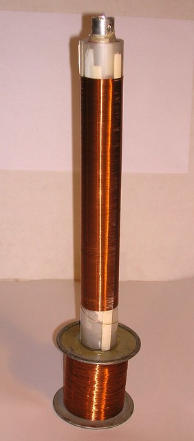
First tests with copper acetate have been performed. The salt was loaded into
a tube, that had worked long (just before its dismantling). May be it was a bad
idea, but I did not want to taint a freshly assembled tube.
In the tube, loaded with the acetate, the discharhe becomes nice blue already
at 150oC. Still no lasing though.
Possible reasons:
- gas-static mode (it is a bit difficult to organize very slow flow at such a
low pressure, so the fist tests vere made without it)
- excess of water in the salt (they say that water vapours do not quench the
copper lasing, but who knows...)
- contaminations in the tube.
A gas-flow spark gap was tested. After some fails with different designs the
next scheme appeared to be operational:
  WWWWWWWWWWWWWWWWWWWWWWWWWWWWWWWWWWW
    XX    XX    XX    XX    XX    XX
    XX\   XX    XX    XX    XX   /XX
  =====  ====  ====  ====  ====  =====
  =====  ====  ====  ====  ====  =====
    XX/   XX    XX    XX    XX   \XX
    XX    XX    XX    XX    XX    XX
  WWWWWWWWWWWWWWWWWWWWWWWWWWWWWWWWWWW
It is a five-gapped sparg gap with pipe shaped electrodes. Its body was made
of a 22 mm OD (16 mm bore) plastic tube. The collars are mold of an epoxy resin.
Electrodes are aluminium pipes 5 mm OD, 2.5 mm bore. For the operation the
spark gap should be connected in place of the HSG in the feeding circuit shown
on fig 25.
The air flow is provided by a small (150W) authomotive tyre compressor.
At first the spacings were set to 5x1 mm, but the spark gap refused to
trigger when pressurized with the flowing air (in gas static mode it triggers
successfully, but does not provide lasing). Then the spacings were set to
0.75 mm (tailor's needle) and the spark gap became operational.
Measurements show that the delay between the pulses in the burst varies from
(rarely) 100 mcs to (rarely) 500 mcs. In most cases the delay is between 200
and 400 mcs.
The laser with this spark gap does not produce long and stable series.
Usually it yields a pair or three bright pulses, a pair or three average pulses
and then dims completely. After a pause it can repeat this again.
Maybe here we deal with instabilities of the breakdown voltage due to the
aluminum electrodes. The hydrogen spark gaps with Al electrodes did not show
good results too.
The lasing with the present design of the gas flow spark gap resembles lasing
with the salt filled spark gap, but the latter is simplier.
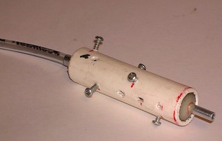
A HV power module was made of some welding invertor and tested. The idea is
generally the same as it was when making a high voltage power supply from a
halogen lamps transformer. Connect directly to the secondary winding of the
power transformer (a large toroidal core with windings made of a very thick
wire). You should connect before the welding rectifier and attach there Your
own high voltage transformer and rectifier. One could expect interference from
the feedback circuits serving for all kinds of protection and stabilization.
In practice it appeared that they make no problems. At least in cheap welding
invertors. One can still expect those problems with expensive and complicated
welding stabilizers.
In the process of trying I fried several samples of homemade high voltage
transformers. And if You decide to build something similar I insist You to have
a fire extinguisher nearby (dont use foam type ones). After those fails it
agreed to work with a transformer having an open core. The core is made of
ferrite rings having diameter 40 mm and being stacked into a column 200 mm long.
The primary winding has 8 turns of triple wire (2 mm each) and the secondary
winding has 1500 turns of 0.5 mm enameled copper wire. The secondary winding
has 5 layers isulated one from another with mylar sheets. (notice from 18.04.2016: this transformer has burned too. Its secondary went overheated and melt the mylar insulation between its layers.) The rectifier is
a kind of voltage doubler. Its capacitors are ones of doorknob type (KVI-3 if
anyone is interested in). It maybe unwise to install mylar or oil-paper
capacitors there, since the reactive power is high.
In this configuration the power supply was able to drive the copper laser
to 20 Hz of the repetition rate, despite the fact that the feeding circuit was
RC type (fig 15) and had very large losses. This figure is twice as high as
my 400W HV unit was able to provide. I don't think this is the limit. Just
the voltage reserve (that is needed to press the current through the ballast
resistors) was a bit too low. I could continue the secondary winding up to
1800 turns and get some 30 Hz of the repetition rate, but the excessive reserve
can be wasteful for the LC circuit (fig 25). It means things stopped again due
to the absence of the resonant charging coil. And its windind process is far
from its end.
However when it will finally be completed, the expected repetition rate
without any additions will be 60 Hz.
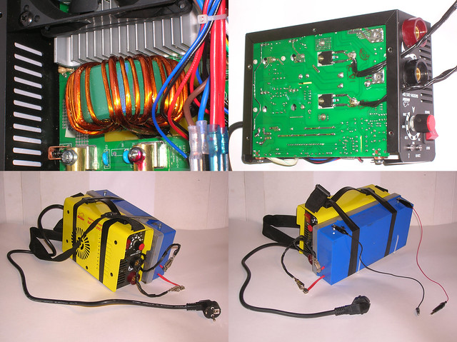
THE CONCLUSION
As it was said by Karmack: "for Your brutal pleasure" here were discussed
and tested six variants of pulse forming network for using with a laser on
the vapours of copper halides:
- Circuit, that produces two pulses using two RC shoulders with different
speed of charging or with different triggering voltage - both ways provide
the different moments of triggering.
- Circuit that generates a seria of pulses (burst) and based upon the usage
of a spark gap having very short recovery time. The latter is achieved by
filling its inter electrode spacing with a porous Al2O3 ceramic.
- Circuit that generates a seria of pulses (burst) and based upon the usage
of a spark gap having very short recovery time. The latter is achieved by
filling its inter electrode spacing with finely grit powder of kitchen salt.
- Circuit that generates a seria of pulses (burst) and based upon the usage
of a spark gap having very short recovery time. The latter is achieved by
shaping its inter electrode spacing to form a capillary filled with the
common air at low pressure.
- Circuit that generates a seria of pulses (burst) and based upon the usage
of a spark gap having very short recovery time. The latter is achieved by
shaping its inter electrode spacing to form a narrow tube filled with the
hydrogen at a slightly reduced pressure.
- Circuit, that produces two pulses using charging/discharging shoulders,
having a self-triggered spark gap in the master shoulder and a controllable
(external triggered) spark gap in the slave shoulder.
All the circuits are made using the readily available materials and
technologies. (Some doubt may be expressed towards the doorknob capacitors. Day
after the day they become more rare and more expensive. But with a certain
persistense one can replace them with some low inductive homemade capacitors.)
All the circuits require average skills for their assemblage.
The best results were obtained with the hydrogen filled spark gap. With it
the laser shows very stable operation up to at least 15 Hz burst repetition
rate. It yields measurable light power and demonstrates the lifetime of at
least 10 000 bursts. Further repetition rate increasement is limited mainly by
the spark gap overheat. If one uses, say, water cooling, it is very realistic
to obtain several hundreeds of milliwats in the beam. By the way I shuild note
that the sealed off hydrogen spark gaps have already demonstrated the storage
time of more than one month (12.02 till 28.03 and still working).
The usage of the controllable spark gap with the external ignition gives
somewaht worse results. With the fresh assembled and fresh tuned spark gap
the laser shows stable operation for up to 50 Hz of repetition rate, However
the average and the peak output powers in this case are less than with the
hydrogen spark gap at 10 Hz of the burst repetition rate. In addition the
attempts to obtain its lifetime longer than 10 000 pulses failed. And it isn't
quite long when the repetition rate is 100 Hz.
The third place is divided between the spark gaps filled with solid porous
dielectric. The Al2O3 spark gap gives rather long series almost without
any dropouts. But the peak and average powers are low. On the other hand the
salt filled spark gap gives a very decent peak energy of the pulses, but the
stability is low and the dropouts percentage is high. As the result the average
power is comparable for the both cases. However I hope that the poor results
are not due to some intrinsic drawbacks of the idea, but merely due to the
lack of the design optimization. Most probably the more perfect design can
be comparable with the hydrogen filled spark gap.
The capillary spark gap filled with air is unable to boast anything but its
perfect stability. The low energy of the laser pulses and instant overheating
even at 1 Hz of the repetition rate make it applicable for the
demonstration purposes only. Its production complexity is comparable to the one
of the hydrogen spark gap, but the yield is way lower.
Finally the circuit with both self-triggering spark gaps in two RC-shoulders.
Neither the high stability nor the high power of laser pulses can be figured
as its distinguishing feature. But it is simple and requires no tuning if
designed and assembled correctly. Additionally the intrinsic variations of
the delay aren't always the bad feature. I.e. at the very first experiments
with the laser You are more interested in whether it is capable of lasing at
all rather than how to get the highest power. And here the delay variation
plays on Your side making some kind of auto scanning of the delay range. And
after You have seen the laser spot You certainly won't let it go away, will
You?
The discussed six variants of the pulse forming network do not exhaust all
the diversity of the ways to get double pulses or series of pulses.
Nevertheless they give You a decent choice at the stage of designing. And it
is well known that the more choices You have, the higher chance of success is.
As for the laser as the whole, then with the exception of the requirements
to the vacuum and to the buffer gas, all the remaining can be made using the
readily available resources and technologies. Including the glass tube, that
can have a form of a tubing from some luminescent lamp, and including the
laser mirrors, where some household mirror can be used in place of the high
reflector (with the minor difference whether it has the fist surface type or
not) and some piece of glass (or two pieces of glass being put one onto
another) can be used in place of the output coupler. The refining of the
pump circuit to have the lowest possible inductance is excessive here, so it
can be designed with much more freedom than in case of some nitrogen laser.
Its a pity, but the required grade of vacuum requires a professional grade
vacuum pump. The reversed fridge compressors and car tyre pumps are out of
the game play here. (One can, however, expect that this possibility will appear
when the neon is used as the buffer gas. Moust authors note that the dependence
of the output to the buffer gas pressure in case of the neon has the second
maximum and it is beyond 100 torr. However the neon gas is for the complete
fans of the copper laser only.)
As for the helium, I can't say that it is out of the access... On the
contrary almost in any town almost at any time one can buy it in the form of
party balloons. And the prices are affordable, especially when taking into
account that the laser can use helium from a single balloon for hours and
hours of operation. (The main losses of the heium are not due to the gas
flow mode, as one might expect. The majority of the helium is used to wash
the vacuum system from the remnants of air.) However the point is not in the
money here... The point is that to make the regular tours for the balloons is
a bit more difficult psychologically than roaming a central square of a city
wearing a pink trousers and a bit easier than to wear lingeries on a beach
(in both cases i mean male persons, since for the opposite gender both of the
actions are common and usual).
If You already have the professional grade vacuum pump and helium (or neon
or argon), You will face no other problems on the way of making Your own
copper vapour laser. In this case I recommend it for You. However at the very
end I can not abstain from adding some fly to the ointment: if everything You
need is just a green laser rated to 10..100 mW, You should better go and buy a
chinese laser pointer. It will be simplier, easier and cheaper. At least now,
when the ban of the lasers having the power higher than 5 mW is rather weak.
And only if (or when) it became strict, it will make the real sense of
assembling a copper laser at home.
CREDITS
All those, who like this web report, or who finds it to be useful, should be
gratefull for the next persons:
- Dmitry Dmitriev, who succeeded to cath up really tons of the misprints.
- Andrew Frankenstein, without whom this web report could simply not appear at
all.
The case is that my project of the copper vapour laser had already lain
without a motion for several years like a Sizif's stone at the top of a hill.
And namely Andrey appeared to be able to push this stone down the hill
successfully, which fact has lead to the appearing of the web-report, You've
just read.
<FIN>
9.01.2017 PS. ARGON.
In the last Year i've got an argon tank, but got no time to check out the
possibility of lasing of the copper-monochloride laser using the argon as the
buffer gas. And finally it is done. The laser was taken from the shelf and
repaired.
The laser was restored in the configuration, based on the hydrogen spark gap
and resonant charging coil (see fig 25). The old tube has certainly turned sour:
the copper monochloride layer on its walls has absorbed the air humidity and
got a deep green color. There was no reason to spend the time in attempts to
achieve lasing with this thing, so the tube was reassembled and filled with a
fresh batch of the copper monochloride. Naturally i did not made a new chemical,
i just used the remains of the one from the previous experiments. All this time
the remains were stored in a jar under the layer of isopropanol, and they
survived successfully (from march to december).
There were some doubts relating to the operationability of the hydrogen spark
gaps. They were sealed off using a hot glue (low molecular weight polyethylene)
as a sealant, and thus could probably fail due to the small leaks, after so
long period of storage. The problem is even worse if we remember that the
hydrogen is one of the most penetrating gases. Sayin beforehand: three of the
four hydrogen spark gaps, that had been filled and sealed off back in march,
appeared to be operational and allowed to get a good lasing. Thats the hot
glue in work...
The repaired laser was tested for lasing wit the use of argon as a buffer
gas. There's no need to describe the procedure of obtaining the lasing here -
it was quite the same as it was for helium (see in this report above ). So
let's go directly to the results. One more thing: I used a common technical
grade argon (so called "welding grade".)
With the remnants of my experience in the field of obtaining the lasing, that
have survived over the year, it was rather easy task. It lased without any
excessive tunings or researches. The temperature range, where the lasing is
obtainable, appeared to be very similar to the one for helium. The same 270..
350 Celcium degrees (measured as the glass tube wall temperature).
With the pressure range of successfull lasing the things are worse. The
lasing could be obtained in a rather narrow area of pressures near the optimum
(about 3..5 torr). I can also say that the optimal pressure is close to the
high border of lasing (and of the discharge stability). In other words the
higher is pressure the better, until the discharge instabilities begin to
prevent lasing. With helium as the buufer gas the laser was very tolerant to
the pressure decreasement. - The lasing output with helium decreases smoothly
with pressure decreasement below optimum. And somewhere at very low pressures
the laser dims out (goes below threshold). On the contrary with argon the laser
has prominent low pressure border of lasing. When the pressure drops below
approximately one half of the optimum, the laser dims out completely.
The output energy (at the optimum of pressure and temperature) is the same
as one with helium as the buffer gas. To estimate the output energy a cuvette
with Rhodamine 6G solution was used. The beam of the copper laser was focused
into the cuvette and it operated as the dye laser. The measure of the
permissible bias from the exact focal point, when the dye laser still lases,
was taken as the value, representing the output energy of the copper laser.
In case of using helium as the buffer gas, as well as in the case of using
argon the permissible shift was +-5 mm (@ 20 mm of the total focal length),
so it means that the otput energy was also the same in the limits of errors.
Thats all. The laser is operational with argon. Not better and not worse
than with helium. The most significant thing was (to my mind) that the glue
gun sealed hydrogen sparg gaps are still operational after almost a year of
storage. This fact shows that even with so low technologies it is possible to
create a sealed off gas discharge unit with decent resource and storage
lifetime.
<< HOME PAGE |