1. Purposes
- The laser was intended to check whether it is possible to construct a DIY CO2 laser using only common materials
- The laser is intended to be used as a testbed for checking gas mixes and other components of DIY CO2 lasers
- The laser is intended for measurements of transparency and reflectance of the very common materials at 10.6 mcm area. (To find suitable candidates for laser mirrors and windows.)
The laser is good as a first home co2 project provided that You have a suitable vacuum pump. High gain makes the laser to be more forgiving to errors in alignment and to gas mix contents. The first experience on forcing CO2 to lase is best to be conducted with this type of laser.
The laser is easy to build and tune but don't expect much of it. Its power and efficiency are low. Hence:
- The laser is NOT INTENDED for material processing.
- The laser is NOT INTENDED for public demonstrations.
- The laser is NOT INTENDED for precise measurements.
2. Laser principle
The described laser is repetitive pulse low-pressure diffusion cooled molecular laser pumped by longtitudal discharge. Why exactly this type was selected to build? Because of:
- High gain.
- Rather high pressure.
- Absence of water cooling.
- Possibility to use plastics and films
Working with untested gas mixtures does not allow to hope for very high gain and high efficiency at usual pumping modes. Worse that, homemade mirrors may have high losses, so even more gain is needed. Needless to say that at low gains laser cavities become very sensitive to alignment errors. Then at any point of view it follows that the higher is the expected gain the better all things become. It means You should direct to the highest gain factor and the longest tube length.
As it is known from TE and TEA lasers technique, high gains might be achieved at high discharge currents (6..10 Amps per square cm is typical for the TEA). However it is at least... difficult to build a transversely pumped laser with a meter long discharge tube. The continuous wave low-pressure laser will hit overheat in a few milliseconds if several Amps current is applied to it. The compromise is the repeated pulse mode. High peak current provides high gain and the short pulse duration prevents gas overheat.
Another advantage of repeated pulse mode (so called Quasi Continuous Wave mode or simply QCW) is simplicity of cooling and temperature control. Typical continuous laser even at threshold currents behaves already as a little boiler. 200..500W of power can easily heat and overheat anything. On the contrary the QCW laser at comparatively low frequency may reach the lasing threshold and stay cool. Here You can use plastic parts, seal all joints with glue gun and omit water jacket. As an addition bonus You will like that this laser is operational at noticeably higher pressures than its continuous brother. This fact in turn allows to use more common vacuum pumps. The rule of arms: "when winning in one place loose in another". Here we give up the efficiency and power to yield operationability with bad gas mixtures and lossy mirrors.
3. Resources
In order to build and use the laser one should have the next resources:
- Vacuum pump
- Peltier-calorimeter
- Micro drill with diamond disc and diamond bore
- Glass tube of a small diameter, about meter of length
- Kit of pipes
- Some vessel to mix and store gases in
- Airgun, saturator or another device for pouring co2 cartridges
- Slightly convex car rear view mirror
- At least one ignition coil
- Laser pointer or helium-neon laser
- Other set of locksmith-carpenter-soldering and garage-kitchen-radio tools
- An assortment of various resources for little crafting
Good but optional are:
- Vacuum gauge
- A set of valves (needle one is most desirable)
As a pump one can use any real vacuum pump. It is not important whether it has rotational or piston type. Also one can use a refrigerator compressor being set for pumping out. However if using this one it must be new or at least at good condition. The elder ones or ones worn off will provide only 80..100 torr and that is not enough for proper laser operation. However if lucky enough You may see lasing even at these pressures. One can also use a reversed (with refurbished manifolds) car compressor for tire pumping.
I personally use a little vacuum pump, that initially was intended for refrigerators and other freon machines service.
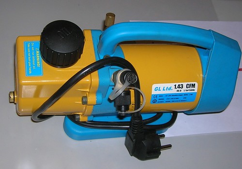
it has 38 mcm top vacuum – definitely excess for the described laser, but if I have one, why should I use another?
DO NOT try to use vacuum cleaner and DO NOT use water-jet chemical pump. (The last one provides water vapors that are too bad for lasing. However if You can feed it with oil the things may come better and probably it will suit.) DO NOT try to use reversed car hand pump. (It really hurts to make suitable vacuum with this one. Probably even if You are athletic.)
The calorimeter (calorimetric power meter) may be of any kind that can measure several tens of milliwatts. (OPHIR’s, IMO’s, etc.) Also a homemade type is good. The one made of a multimeter and Peltier-cooler.
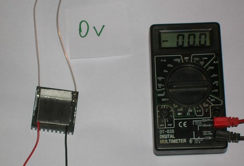
It was written here how to build it. Without a calorimeter it will be almost impossible to detect lasing. The carbon paper is only to break Your hopes. At first starts there will bee only a low power, that is not enough to burn anything.
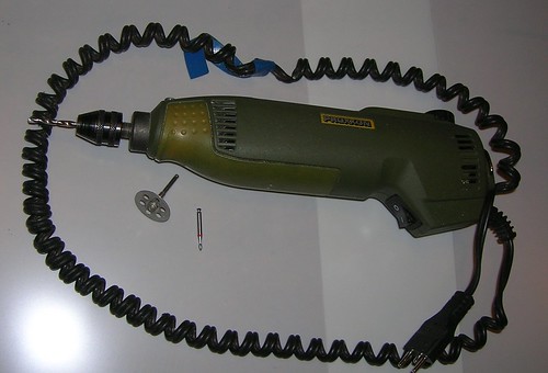
Micro drill with diamond disc and bore is needed mainly for production of mirrors, however it will be useful for other small working (e.g. for cutting fitting pipes)
Glass tubing for the laser cell should ba about a meter of length (remember that we want highest gain per path). The optimal diameter is about 8 mm but it is rare. A bit worse but good enough is a tube used in luminescent lamps with G5 base (outer diameter is 12 mm). Those lamps are rather hard to find too. The most wide spread are T5 based lamps (outer diameter is 16 mm). This one is used for the described laser.
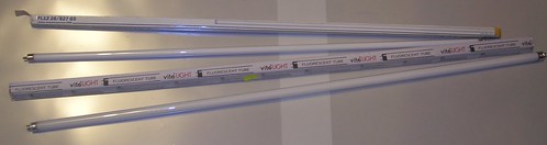
Using the diamond disc cut off the endings with filaments and seal them tightly into a polyethylene bag. The filaments contain noticeable amount of mercury. You should trash them safely or either safely store them for Your future project with mercury vapors laser. (Note that when lamps aren’t new the mercury may be spread along the tube. So it is safer to disassemble new lamps.)
PVC or silicone pipes are good for use. Rubber ones will lead to a bulky design and should be avoided. The pipes must be rather hard for not to pinch under the atmospheric pressure. The pipes for car glass washing system are suitable.
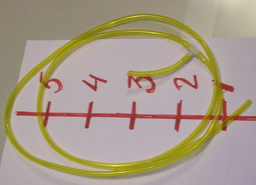
Those pipes have 4 mm inner diameter. So the same must be all fittings.
As a gas vessel one may use a car tire. Also well known for the lasers’ fans Jarrod Kinsey uses a party balloon.
http://www.flickr.com/photos/12049698@N02/4610061580/in/set-72157624001202153/
(also see google-search with "co2 laser human breath" keyphrase)
The dry carbon dioxide can be got from co2-cartidges for ariguns. Fire-extinguishers also suit well. The most simple way to pour a cartridge is to use a home saturator.
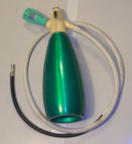
In ancient times there once was a device for home making of soda water. It was called “saturator”. Nowadays it is hard to find. As an alternative You may put a pipe on an airgun’s barrel and in the meanest case shoot up the necessary volume of gas. More advanced technique is to chock the hammer in the pressed position and smoothly pour the cartridge. Dependently to the model of airgun it may be necessary to seal leakages with plasticine. In any case the games with pressurized gases aren’t the most safe action in the world. If You are a kid You should consult with adults how to do all correctly and safely.
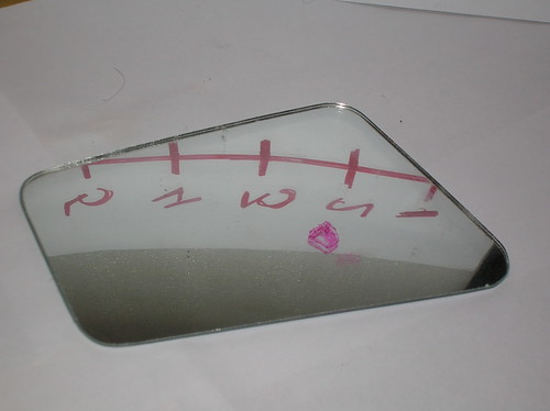
The rear view mirror may be purchased in a car shop. Not all mirrors are evenly good. Three conditions:
- The mirror must be slightly convex. Too convex mirrors won’t work.
- The mirror should be easy to disassemble. And the layer of paint on its backside should be easy to remove.
- After removing the paint there should appear smooth glossy aluminium coating. (Some mirrors have dull coating instead.) After that the metal side of the mirror will now be its face and the glass side will be its rear. Here the convex mirror becomes concave.
Using the rule of thumb method choose an appropriate mirror. Like this one:
Using glass-cutter or a diamond disc cut some square pieces from it. They should be about 20x20 mm sized. Drill some of them with a diamond bore for 3mm holes in their centers. Better to make several pairs of mirrors at a time, because there is a considerable probability of failure during drilling and paint removing.
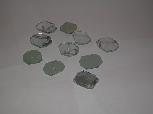
Put the mirrors into a tight jar and cover with a solvent layer. Usually dichlorethane is the best, but sometimes it is contaminated with muriatric acid, and removes aluminium layer as well. Acetone works slower (it takes several days to remove coating). And in the most neglected cases one should try to  the type of the solvent. the type of the solvent.
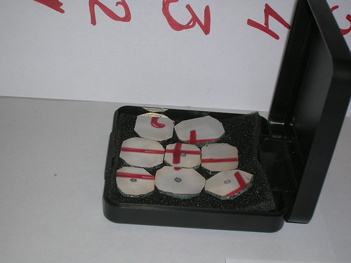
It is recommended to select the best mirrors. When it is sunny, take the mirrorlet (touch only the edges! DON’T touch the aluminium layer!) and aim the sun reflection onto a wall. Varying the distance between wall and mirror find the focal place (when the sun image becomes sharp). If the sun image is too elongated (elliptic) trash the mirror. If the image is too dim (when compared with given by another mirrors) trash that one too. Also You should trash the ones that give image with clearly seen diffuse halo. The focal length is usually about 1.5..2.5 meters. And among 3..4 pieces You will definitely find a good one. The process of making and selection of mirrors is rather boring but it is nothing when compared with attempts to polish one from a copper coin or attempts to put silver coating onto the goggle lenses.
The ignition coil must not be electrically weak. Do not use motor cycle ones or ones from light weighted cars. If You have a pair of coils it is better.
Alignment laser – You can use e.g. He-Ne type. However it has doubtful advantages when compared with a common laser pointer, because there’s no need to make alignment by interference rings. When choosing a pointer as an alignment laser, pay attention to its battery lifetime. Better to find one with power adapter. Too powerful (>10 mW) green pointers cause eyes ache after the alignment, so use the reasonable power.
At least we’re finished with resources. Lets see the design.
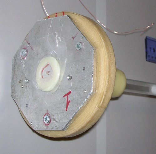
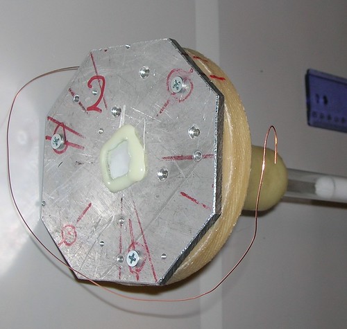
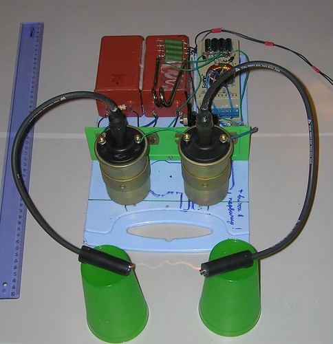
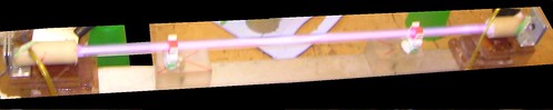
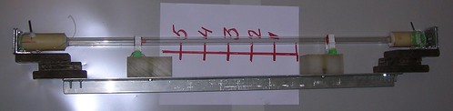
4. Laser tube design

The laser tube design is shon on the figure above. Essentially it is a glass tube glued between two endings (alignment units). The gluing is made by glue gun (thermal glue), it showed itself from the best side when vacuum sealing. Leakages are possible in the laser but undesirable. In the first place they interfere with trying to keep known mixture contents. Here is the design of an alignment unit:

If You have handy flanges with orthogonal pipes of appropriate diameter – use them, don’t bother on making flanges yourself. However I haven’t anything suitable in range, so after two weeks of searching I said some selected words and made the flanges myself. I used epoxy resin enforced by band and herringbone tape.
The mirror mounts are made of 4 mm aluminium plate. Some hard plastic (e.g. Perspex) will suit too, but it should be thicker. As a seal (and as an elastic element) some rubber toilet washer of appropriate diameter was used. No other springs are foreseen.
Alignment screws are with M4 thread. The nuts are epoxy glued in order to fix down. If You can securely fix M3 nuts (for example if using metal flanges and the nuts are pressed in) than You can reduce diameter of alignment unit to about 50 mm. For the M4 the optimum is 80..100 mm.
Inlet and exhaust pipings are also placed on the alignment units. In principle one can drill the glass tube and glue the pipings into the holes – it is only by preferences.
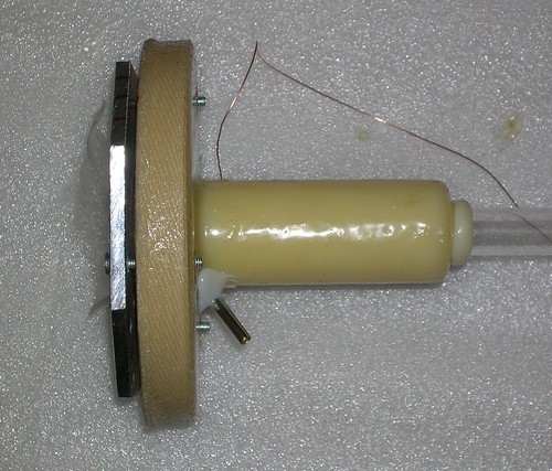
The electrodes are made of thick aluminium foil (or thin plate). The thickness is 300 mcm. The strip of this foil is rolled as a sleeve with a diameter to provide minimal gap between it and glass tube walls.
Electric terminals are made of uncoated copper wire. They are lashed (do not glue, do not solder) to the electrode sleeves. At first the terminals should be long enough (30 cm or more). The diameter of wire is a deal of choice. No 23..30 AWG will be good. When using full-metal alignment units it is probably optimal to use themselves as electrodes.
Assemblage hint. Insert the aluminium electrode sleeve with already lashed wires into the glass tube. Then (here is what the long wiring for) needle the wire through the hole (specially drilled for it in the body of the alignment unit). Then brush the end of the glass tube with glue gun, and before it has congealed, insert the glass tube to its place. During this process You need to gradually pull the wiring. (Keep an eye for not to pull out the aluminium sleeve from the glass tube.) When the glass tube is glued in place, seal also the wire terminal.
After both alignment units are installed and assembled – glue thin transparent plastic stoppers in place of mirrors. Cut them from CD-case cover for example. It is too early to install the mirrors.
Lets check for leakages. Pump the tube off and pinch inlet and exhaust pipes. If You have a vacuum gauge then watch the pressure. The tube should leak not more than 20 torr per hour. It is acceptable. If You have no vacuum gauge, but the power unit is assembled, You can use it to judge about leakages. The discharge in the tube should keep its look and color for a reasonable time. (Several tenth of minutes if it is low pressure glowing discharge with strata and several hours if it is contracted high pressure discharge).
If the tube leaks, then disconnect it from the vacuum pump, and go to the bathroom to seek the leaks by typical garage method – pump it up, put in water and watch the bubbles. Do not work hard when pumping. The tube will endure 0.5 bar. Rise the pressure above and You will probably break mirror mounts, strip off washers or stoppers. Avoid water inside the tube. It will be difficult to extract it from there.
When got rid of leakages You may glue the mirrors. You will have to glue them without leakages, because bathing of the assembled laser is a bad idea. You can only use dry methods for leak checking so You will know that there is a leakage but You will not know where it is. First of all glue rear mirror to its place. If it leaks detach and glue back. Then glue the forward mirror and a polyethylene film above it. Check for leaks again. In case of leakages – detach and glue back.
Here is how the assembled alignment units look like:
5. Power unit
Here is the power supply schematics:

R1 – halogen lamp 500W 220V
U1 – electronic transformer for halogen lamps (Feron type good but other types are also usable) rated at 250 W
Tr1 – is wound on a main core from other electronic transformer for halogen lamps of the same type as the previous one. Primary is 4 windings of #18..19 AWG wire. Secondary is 200 windings of #28..29 AWG wire. (External transformer is used only for not to interfere with internals of electronic transformer. If You feel free with radiotechnique You can simply modify transformer inside the electronic transformer for needed output voltage)
R2 – 86 Ohm (spiral of 500W cup boiler)
VD1, VD2 – HER308 diodes
C!, C2 – electrolytic 10 uFx450V.
C3 – ceramic or foil type 2000 pF not less than 2 kV rated.
SCR1 – thyristor rated to 1100V and 20 Amps
SG1 – low voltage spark gap rated to 250V (e.g. NS2R-250-A1), feel free to use a suitable dynistor instead, but you will need to modify the schematics properly,
C3, C4 – metal-paper ones 10 uFx1000V.
Tr2, Tr3 – two ignition coils connected in series.
resistive divider R3, R4 should be chosen so that SG1 gap triggers when C3 and C4 are charged at 700..800 Volts. (R4~100 kOhm, R3~300 kOhm)
The purpose of the schematics is to charge C3 and C4 capacitors (20 uF in total) up to 750 Volts and then rapidly discharge them through primaries of the ignition coils. And repeat it many times per second. Any scheme that can do it is usable as laser’s driver. It also should be mentioned that the output of the schematics may be designed with a single coil, but it will be less stable at higher voltages (single coil is easier for breakdowns) thus You will be limited at lower pressures in laser tube.
Correctly working power unit gives ~4’’ long spark with repetition rate about 10 Hz. The spark is fat with a strong but soft sound. The show is rather scary.
The output voltage is chosen rather high ~100 kV to provide breakdown in laser cell at comparatively high pressures (up to 80..100 Torr). Of course it is not the optimum. If You are interested only in output power and You got a good vacuum pump then stay at ~30..40 kV. OTOH if all You got is the old fridge compressor, the 100 kV output is Your last chance.
The power unit should be turned on from a safe distance. And when it is switched on don’t come close to it or any parts of laser being under voltage. In theory the power unit is uncoupled from ground and there is no tendency for breakdowns into the pump trough feeding pipes, but it is strongly recommended that the length of each pipe was over 5 feet… Just for overcare.
When shocking for a short time such a power unit usually can not kill a human (but no warranties at all – everything depends on health state) but injuries will be severe. As a rule the contraction of muscles damages bones and teeth. Imagine a shocker rated a hundred times more powerful than the most powered one among the ones You ever saw at a shop. This is comparable to power of this unit. So please be careful. Always keep in mind, that not only the direct touch is forbidden, but also it is very risky even to approach to any parts under the voltage – You may be hit by a spark.
6. The Alignment
To keep it easy the laser has stable cavity. Its mirrors are focusing. There radius (doubled focal distance) is greater than distance between mirrors. It means that the cavity formed by such mirrors does certainly fall into area of stability. Without proper knowledge don’t use convex mirrors or too strong concave ones. Unstable resonators are too hard for the amateur. In principle the output mirror may be plano. It slightly focuses output beam and makes easier to obtain beam patterns on a carbon paper. However it works good only with semitransparent output mirror. When output mirror is a metal one with a coupling hole, to say simple, it is harder to hit the hole with thinner ray – the laser will be harder to adjust.
The alignment is made by means of typical for all lasers method – by overlapping spots of beams reflected by front and rear mirrors.
There are however some details to pay attention:
- The alignment is to be made under vacuum (Otherwise it is unknown where the beam will walk when air pressure will be applied to alignment mounts).
- The alignment of rear mirror is to be made when the front mirror is dismounted. To make the alignment needling the beam through the coupling hole is the same thing as to hang wallpaper through a keyhole. The laser must be tightly fixed in order not to break tuning when mounting and dismounting the mirrors.
- During alignment all pipes and wires should be already connected to laser. (THE HIGH VOLTAGE MUST BE SWITCHED OFF!!!) Otherwise it is easy to break all tuning when connecting all communications to the laser.
The alignment is made in three stages.
- Needling the alignment laser beam through the tube of laser being aligned (or either if You have movable fixators o the tube, You may don the tube onto the beam – it is easier)
- Placement and tuning of the rear mirror
- Placement and tuning of the front mirror
After alignment is done don’t remove the alignment laser – it will show You where goes the invisible infrared beam of our CO2 laser.
A builder’s level is handy for use as alignment laser. Its tripod allows to easily adjust height and angle of its laser (well, at least it is designed for this).
You should stick a piece of paper with a 0.3-0.5mm hole onto a face of alignment laser. The paper will serve as a screen where You will observe the reflected beam. Obvious that the hole must be placed over the output beam of the alignment laser. When the hole has less diameter then the alignment beam it helps to keep the beam ‘cleaner’. To stick the paper use plasticine or chewing gum – it allows to move the paper in certain range for better coincidence of the hole and the beam.
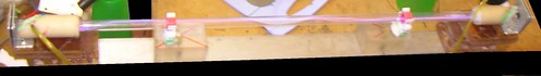
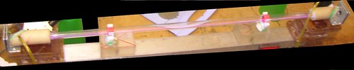
- Fix the CO2 laser. Remove endings with mirrors (unscrew alignment screws for that). Place the alignment laser at 4..5 feet from the laser being aligned. With a help of all handy means and known mother make the alignment beam to pass along the axis of the co2 tube:

The beam must not touch walls of the tube. Bumps are forbidden.
- Screw in place the plate with rear mirror (with its washer of course).
Hint: the washers should be glued to mirror mounts by rubber adhesive. After that they won’t drop down at the very moment.

Instead of front mirror take a transparent plano plane and jam onto a front seal. No need to glue – it will be sucked well with air pressure. As a temporary window You can use a piece of plastic from CD-box covering.
Pump the air out of the laser. No need to reach high vacuum, because the forces due to athmospheric pressure are nearly the same for high vacuum (say 0.1 Torr) and for the low vacuum (say 70 Torr).
By turning the alignment screws make the direct and reflected beams to become coincident. (Force the reflected beam to hit the hole in paper from where the alignment beam comes out). Again avoid beam bumps against the tube walls.
Hint: when the tube still contains luminescent layer it is easier to see when the alignment beam hits its wall and where it happens.
Act carefully for not to break the achieved tunings.
Let the air come into the tube. Watch the reflected alignment spot. When done properly it almost does not shift with pressure changes. If it shifts more than by 1/10 inch repeat the alignment procedure with more tight screwing the alignment plate. If You can not stabilize the alignment by increasing force on alignment screws, replace the seal washer with harder one.
- Remove the temporary window, and screw in place the plate with output mirror. Again pump out the air and tune alignment screws for direct and reflected beams to be coincident.

Here are the specialties:
- for the alignment beam the front mirror is convex and it will scatter the ray.
So You must aim the center of this large scattered spot onto the hole in paper screen.
- The beam can either completely falls through the coupling hole in the front window (and there is no reflection at all) or a part of the beam falls through the hole and it is hard to say where this asymmetric reflected spot has its center.
It is desirable that the alignment beam in its section near the front mirror has a diameter slightly greater than the diameter of coupling hole. If then the alignment beam uniformly radiates the hole, the reflected pattern is simple – round dark spot surrounded by round bright halo. In this case You need to aim the center of this dark spot (shadow of the coupling hole) onto the hole in paper screen.
If the alignment beam irradiates the coupling hole asymmetrically, You should either search for the center of the reflected pattern using Your intuition, or revise the alignment from the very beginning with proper placement of the alignment laser.
However don’t be afraid of the alignment process. The laser operate well when the spots of beams reflected by front and rear mirrors biased one against another for 1/3’’..1/2’’ (when paper screen is at 2.5feet from laser). It is rough enough to be almost careless about the alignment. Exactly for this forgiveness we choose the stable cavity type.
If You do not move laser from one place to another and simply keep it in place where it was tuned, the alignment is stable for several days.
7. Gas mixture
1:1:9 – the ideal mixture for low pressure continuous wave laser (the first digit is for CO2 concentration, the second is for nitrogen concentration, and the third one is for helium content. All parts are volumetic.) However helium is rather hard to obtain at home. Shopping raids for party balloons bother definitely. Pure nitrogen is even harder to get. All known methods of its generation require chemicals that are in turn hard to obtain. One can say why not to simply buy gas cylinders or liquid gas tank? Just imagine: You are fourteen years old, You study at school and Your parents are not very fond of Your laser hobby. You are lucky if “uncle Bob” has job at the local gas station and he is a friend of Yours. If not – it’s a stalemate.
For not to keep it longer: the first success in lasing this laser was with almost pure carbon dioxide from CO2 airgun cartridges. The gas was contaminated mainly by air left in pipes and tubes. And the air content was less than 10%. It did about 1 mJ per pulse, that gives 10 mW at 10 Hz repetition rate. (Pretty low but enough to see by calorimeter readings.)
Yet haven’t succeeded in lasing of “combustor”.
Yet haven’t succeeded in lasing of known from literature mixture of co2:air 1:5.
Yet haven’t succeeded in lasing of co2 from baking soda with citric acid (obviously the gas requires drying)
The highest power among simple mixtures gives co2:air 2:1 (about 3 mJ per pulse)
More complicated is mixture of co2:dry air:wet air (dry air is taken from the atmosphere when low humidity weather; the wet air one can breath down directly from lungs). This mixture gives about 7 mJ per pulse.
Keep in mind that oxygen-containing mixtures rapidly degrade due to nitrogen oxides accumulation. At 10 Hz power drops twice in about two seconds. So the stable lasing on high oxygen-containing mixtures is possible only in gas-flow mode. However the mixture is cheap and the rate of its consumption is low, so it shouldn’t bother.
Interesting results are with mixture co2:”combustor” 1:1 – 2:1. At first the mixture degrades quickly (from ~5 mJ per pulse to 2..3 mJ per pulse after several minutes) and then it works stable for a long time (several hours, may be even more but I haven’t tested). I.e. the resource of this mixture in the sealed mode is comparable to the time of contamination due to tube leakages.
The “combustor” could be made the next way. Get cotton dipped in some alcohol, put it into a small boat and sail it e.g. in a bathtub. Ignite it and cover with a glass (not plastic!) jar. Then wait until the oxygen in air under the jar will be burned out. Odd, but the reduced volume of gases in the jar (measured by water surface level in the jar) well responds to full combustion of the oxygen (really it is the quite opposite evidence: some hot gas bubbles out of the jar so if the combustion is full the volume of the left gases should be LESS than 80% of initial air volume.) After the combustion is finished use one or another way to get the gas mix from the jar (presumably mix of N2, CO2, CO and ugly contaminations) into the gas mix vessel. The “combustor” hasn’t shown to be working on itself, but when diluted by additional dry CO2 in can work as nitrogen surrogate to some extent.
The methods of mixing gases and ways of pumping them from vessel to vessel are a free area for Your creativity. Keep in mind however that it is enough to bubble a gas through the water even once for the gas to capture the water vapors up to complete saturation. Sometimes it is useful (e.g. for humid mixtures) but in other cases it gives completely inoperable gas mixture.
One more note: when mixture is prepared, You probably want to keep a suitable volume of it for future use. - Don’t. As the experience shows, the only one way to store the mixture is to keep it in a clean and tight gas cylinder. Inside tire the mixture half-dies throughout a week. Balloons do even worse. So let’s consider that the gas mixture is not for storage, and anytime we use the laser we prepare the fresh mixtures.
8. First light. (Hunt for lasing.)
Fun start! Well then, lets assume that the tube is assembled and aligned. The power unit is assembled, tuned, and connected to the laser tube. Vacuum pump ready and also connected. The gas mixture is cooked and waits for its hour inside a tire or balloon. A battery in calorimeter power meter is fresh.
Put the Peltier calorimeter sensor so that the alignment ray hit its heat sink exactly opposite the center of its sensitive area. Turn its multimeter on and wait for readings to get stabilized.

All ready for the start.
 the inlet pipe (the one connecting gas mix vessel with the laser tube) the inlet pipe (the one connecting gas mix vessel with the laser tube)
Pump the air out of the tube until the top obtainable vacuum.
the exhaust pipe (the one connecting vacuum pump with the tube)
Gently releasing inlet pipe let gas mixture to come into the tube.
the inlet pipe.
Evacuate again. (Of course you need to release exhaust pipe to be able to pump out.)
This is the washing procedure. If Your top vacuum is less than 1 torr then a single washing cycle is enough. With a weak pump repeat the washing cycles several times.
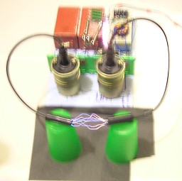
Again let the gas in,  the inlet pipe and gently releasing the exhaust pipe catch the pressure when the power unit can already produce spark in the tube. If You have a vacuum meter hit pressure range of 60..80 torr. Without manometer periodically turn the power unit on for a short times and pump out until You see sparks inside the tube. the inlet pipe and gently releasing the exhaust pipe catch the pressure when the power unit can already produce spark in the tube. If You have a vacuum meter hit pressure range of 60..80 torr. Without manometer periodically turn the power unit on for a short times and pump out until You see sparks inside the tube.
At high pressures the spark in the tube is snaky. Here is how it looks like:
Some mixtures (partially the pure co2) already lase at those pressures. However the power is too weak.
When the breakdown in the tube is reached, the power unit is safe to be turned on for a long time (the spark limits its output voltage and reduces chance of internal breakdowns in the ignition coils). Switch the power unit on and continue to reduce pressure (Inlet pipe is ed, exhaust pipe is released.)
When the spark becomes straight and starts to slowly increase its diameter the pressure usually responds to maximum lasing power (~20 Torr)
With further pressure reduction the discharge becomes diffuse and lasing energy smoothly goes down.
At lower pressure the resistance of the discharge decreases that leads to reduction of useful (the one put into gas) part of total discharge energy. The main losses then are Joule ones on ignition coil resistance. At ~5 torr the energy drops so greatly that it becomes below the calorimeter errors.
Learn how to catch the necessary pressure with exhaust pipe being released. (However with strong pump it may be needed to leave the pipe slightly ed.) Watch the pressure by vacuum meter or by form and color of the spark. When You are skilled enough in maintaining the correct pressure with continuous pumping out and leaking in, You can use the laser in gas flow mode. In this mode You can utilize the fast degrading mixtures (the ones containing air.)
Orienting to the calorimeter readings find the mode, when output power is highest. Vary the total pressure in tube and the rate of gas leaking in. Get skilled in maintaining this mode for a long time.
With a certain experience You will be able to define the proper mode by observing the discharge form and color. When done You may try to replace the calorimeter with another targets. E.g. carbon paper or either concave mirror with something in its focus.
For radical enlargement of the power:
- Find the best for Your conditions gas mixture and its optimal pressure.
- Find the breakdown voltage for Your pressure and mixture.
- Build a new power unit for the chosen voltage and for higher repetition rate.
(The energy in storage capacitors may vary with mixture and pressure, but it usually should be over 2 Joules for this size of tube. Since You can’t change the winding ratio of the ignition coil, only one way to change output voltage is to change voltage on the storage capacitor with corresponding changing its capacity.)
9. Some data interesting for home CO2 lasers design
Here is the results of my measurements of some handy materials (I’m sorry for large errors, but sic.):
| Material |
Transmission for 10.6 um
|
| Cap of
Pringles jar (transparent polyethylene ~1 mm thick)
|
About 10%.
Transmission is very noticeable but below measurements threshold.
|
| Household polyethylene
bag (measured thickness ~20 um)
|
90±10%
|
| Teflon strip
(measured thickness ~20 um)
|
80±10%
|
| Rubber party
balloon (puffed up to common level), transmission through both walls
|
60±15%
|
| Fluorspar
optics (lens) 1 mm thick
|
30±10%
|
| Mylar foil,
100 um thick
|
Less than 10%
(transmission unnoticeable)
|
| Acetate foil,
100 um thick
|
Less than 10%
(transmission unnoticeable)
|
| Mylar foil, 10
um thick
|
Less than 10%
(transmission unnoticeable)
|
| Transparent packing
duct tape
|
Less than 10%
(transmission unnoticeable)
|
| Polystyrene
1.2 mm thick (cover of a CD-box)
|
Less than 10%
(transmission unnoticeable)
|
During measurements the calorimeter was at 2..3 feet from the sample, so the directional transmission was measured (all scattering to high angles was treated as losses). It appears that cloudiness and turbidity of polyethylene and Teflon samples does not matter for CO2 radiation transmission in range of errors. However the transparent samples are more useful as windows because with less scattering of red beam it is simpler to make alignment.
Probably You are already thinking about a laser with polyethylene windows at tube endings. Here are the data how plastic films affect lasing when being placed between mirrors (inside the cavity). This was measured on the analogue system, but with mirrors uncoupled from tube endings. The tube has completely the same design, but with one difference: its endings are shut not by alignment mounts, but by Brewster KCl windows.
The tests were made with CO2:air 2:1 mixture in gas flow mode. The film samples were placed orthogonal to cavity axis (I mean not at Brewster angle) and also the films were slightly battered. No special efforts to make them straight and smooth were applied.
| Sample |
Lasing power loss
% from maximum
|
| Polyethylene,
20 um 1 layer
|
No reduction
observed
|
| Polyethylene,
20 um 2 layers
|
No reduction
observed
|
| Polyethylene,
20 um 4 layers
|
20% |
| Teflon, 20 um
1 layer
|
No reduction
observed
|
| Teflon, 20 um
2 layer
|
20% |
| Teflon, 20 um
3 layer
|
50% |
| Teflon, 20 um
4 layer
|
oscillation failure |
Two conclusions:
- Polyethylene and teflon are both usable as intracavity windows when the tube is long enough to compensate losses. Teflon is more durable to temperature loads, and polyethylene is more durable to mechanical loads (at least my experience says so). 20 um teflon naturally failed to endure vacuum stress at bore diameters more than 3 mm. Too low for making full scale window, but probably suitable for closing coupling holes in front mirrors when You plan to make a tube rated for rather high power. Otherwise 20 um polyethylene endures vacuum at bores up to 6 mm, so if You have such a thin tubing, You really can put polyethylene windows on its endings.
- Also the obtained data can be used to make rude estimations of laser gain. It appears to be at about 0.5 % per centimeter. (For details how this estimation was made refer to the Russian version of this guide.) Yes, it is comparatively low even in pulsed mode. Just to compare: scientific literature for the same laser in good conditions with clean and optimum mixture mentions gain coefficients at about 1..1.5% per cm for continuous mode and 3..4% per cm for pulsed mode.
Since we have small gain even in the pulsed mode I would say it is risky to try to reduce the tube length. For the correct calculations of minimal tube length one should know the losses at mirrors. The precision of my measurements however is too low to see them. (I may estimate the described aluminium mirror reflection somewhere between 90% and 100% for 10.6 um, but it is all I can say.) For the worst case it means that 20 cm long tube will be at the very threshold of lasing. But for the amateurs I would recommend above 40 cm.
10. Again, why not TEA?
Transverse discharge atmospheric pressure laser is too complex. Yet not even in its design. It has too many parameters to vary. Mixture contents, pressure, discharge time, impedance of feeding circuit… That’s a very incomplete list of them. E.g. my first DIY TEA laser got lased almost half a year since that I learned how to get stable volumetic discharge.
The pulsed longtitudal laser is much simpler. There exist only two roots of evil: improper mixture of improper alignment (provided that there are no leakages already). The alignment problems are greatly reduced by stable cavity (concave mirrors) so almost all problems are only with gases.
When gases, mirrors and other auxiliary problems are solved with this kind of laser You surely may proceed to building the TEA one.
<< HOME PAGE |


