|
Laser Power Meter is Eyes and Ears of any Laser builder. It is always good to know how powerful Your laser is. But moreover in some cases (e.g. see CO2 laser) You only can tune up Your laser with a help of some measurer, sensitive in desired spectrum range. In these special cases if You have no suitable power meter You are just unable to make Your laser to lase.
Why exactly calorimeter? Isn't it simpler to take a photodiode or photoresistor? The short answer – nope. There certainly are some semiconductor sensors suitable for our purposes. But they are extremely rare (photon drag detectors), insensitive to interesting wavelengths (usual photodiode or photoresistor), or either very unusual in maintenance (cryogenic ones).
On the other hand calorimeters are easy to make and calibrate, sensitive to all radiation that produces heat (i.e. to ALL radiation of suitable power), and easy to use. The very drawbacks are:
- The first one – too low measurement speed. You will always know average power of Your laser (or total energy per pulse) but no way You could measure peak pulse power, or pulse duration.
- The second one – You need a considerable amount of heat for the calorimeter could measure it. So Usually tenths of milliwatts. Low power laser pointers and nitrogen lasers will be out of measurement limits.
Building thermoelectric calorimeter
↑
The most spread laser power meters are utilizing principles of thermoelectric calorimeter. Way earlier it was too hard to build such a gauge on Your own. (You'd get crazy on welding several hundreds of thermocouples, installing and wiring them and providing good heat sink where it is needed.) The output would be several millivolts per watt of accident laser power. It was needed to use a good and linear amplifier. Nowadays 90% of work is done for You. You only need to buy a Peltier cooler. (They exactly are a stock of thermocouples and based semiconductors, not on metal pairs.)
I. Resources
↑
The resources are the next:
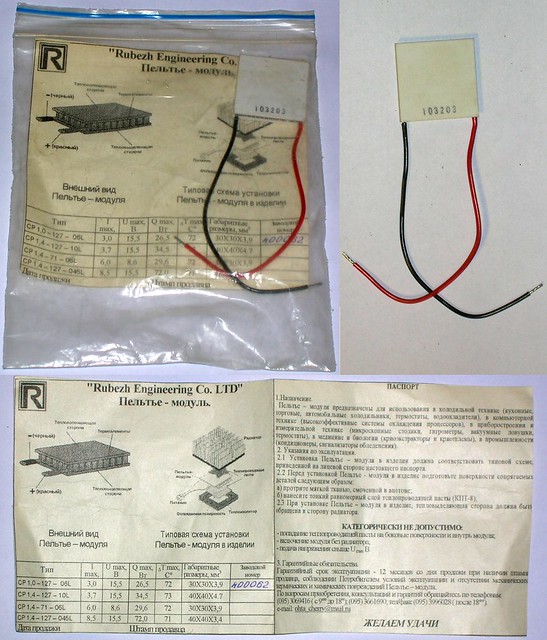
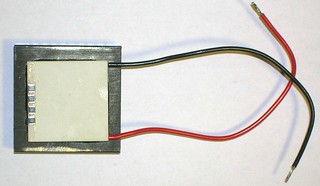
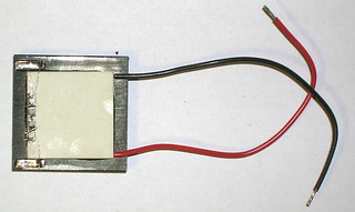
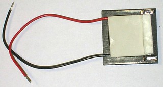
- Peltier element – it is used as a processor cooler in notebooks, and it may be bought in radio elements stores or on E_b_a_y. It costs 1..15 dollars. The next picture shows how looks like:
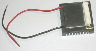
- The next resource is air-cooled heat sink rated at 5..10W. It looks like that:
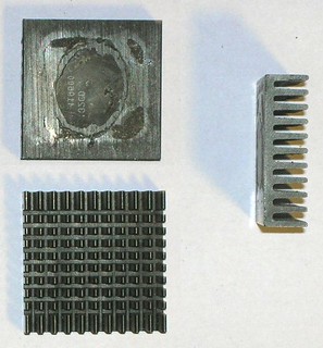
This one was bought at a local market for about 10 cents. Its previous owner seems to have scavenged it from a video card or chipset on PC motherboard.
- Several planar resistors with total resistance of about 500..1000 Ohm rated for several hundred milliwatts. They are easy to get from many electronic parts stores or again from E_b_a_y. The skilled ones in electronics just have such a resistors.
- Multimeter with millivolts range. (The digital one is better – it usually has high impedance input)
It looks like that:
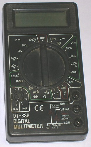
You may fish it from a garret, garage and so on. In the least case you can buy it at nearest hardware store. It costs several bucks.
- A glue (better the heat conductive one) – hint is to mix epoxy resin with aluminium or bronze powder or grinded graphite. You also can use some "alusil" or other commercial silicone heat conductive composition, but it is not durable, it is sensitive to shocks, and it uses to overdry and become crisp in a year or two. It also should be noted that if You are going to measure only far below of a Watt, You shouldn't bother on the glue's heat transmittance. Any glue has enough transmittance when forming thin enough layers.
- A pencil
- A piece of PCB material
- A piece foam plastic
- Wires
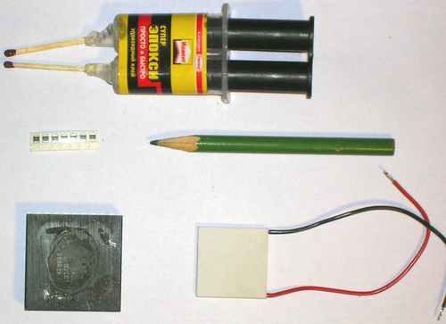
Here is just all You need:
II. Assemblage
↑
- Mix the glue and glue the Peltier element onto the hat sink. It is better to glue the resistors also in this operation – it allows not to make two glue mixes. You will obtain nearly the next:
Pieces of PCB material (for calibrator terminals) You also may glue in the same operation. Of course it is better to use commercial leads if You have ones in stock. Wait for glue curing.
- Take a solder, piece of tin-plated wire, tin, flux, etc… Solder the resistors in series, and then make wiring from the ending resistors to terminal plates.
(If watching carefully One may note that on this picture two resistors are shortened. Sorry, my fault. I thought that I was taking 100 Ohm rated resistors and only after they were glued down I've noticed that they are 1 kOhm's. This mistake will slightly raise the errors in calibration due to smaller heat-contact surface between the resistive calibrator and the Peltier element.)
- Take a piece of foam plastic, and cut a heat insulating covering from it. The covering then is to be glued upon the resistors. After that they can drop heat only to Peltier surface and not to air.
Again wait for glue to cure.
- Make the working surface black.
Methods of blackening:
Poor man's:
- Brush with drafting ink (reflects about 10%)
- Smoke above a candle (reflects about 10%)
- Draw with a pencil (reflects about 20%)
Major ones:
- Rub with cotton, dipped by AgNO3 solution, and then rub with cotton dipped with sodium sulfide solution (reflects about 5%).
- Rub with cotton, dipped by palladium chloride solution (there exists such a liquid for treatment of printed boards), and then treat with a flame of gas torch (using the reducing zone of the flame). Palladium black reflects less than 1%.
Average:
- Use laser printer toner as such as for printed board making. This is better to be done at the first stage before any further assemblage, otherwise it will be very inconvenient
For the example I have chosen a pencil. A simple method, that gives may be not the best but stable results.
- Thats'all folks. It remains only to connect the wires of the Peltier module to the multimeter, connect wiring from the resistors (the calibrator) to a power source of known voltage and to make calibration.
III. Calibration
↑
- Here is the calibration schematic:

It is better to use a personal computer power supply. It has high precision and it is easy to obtain. It gives 5 volts (between red wire and black wire) and 12 volts (between yellow wire and black wire) Solder two wires (long enough for easy use and thick enough for their resistance be negligible) to calibrator terminals.
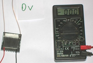
Connect the wires to 5 volts from power supply. At this time yet keep the power supply switched off. The polarity is of no importance (resistor behaves equally under any polarity). Connect wires from the Peltier module to the multimeter. Also do not bother about polarity yet. Switch the multimeter to its 200 mV range. Wait until the temperature (multimeter reading in millivolts) becomes stable.
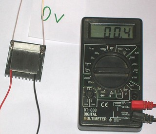
Write down the "zero" value.
- Turn the power supply on. If the readings begin to go down (instead of rising up) here is the very time to change the polarity of connection of the Peltier to multimeter. (You will also need to measure zero value again.) However if You don't worry about this 'minus' sign, You may leave things as they are.
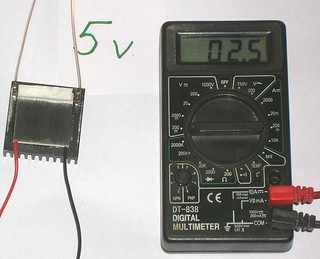
For the shown device the input power is W=U*U/R=5v*5v/2000Ohm=12.5mW.
The"scale interval" k=W/(readings – zero value)=12.5/(2.5-0.4)=6 mW/mV.
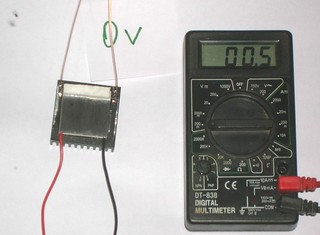
- Switch off the power supply. Wait until readings settle. At the same time reconnect the calibrator wirings to 12 volts output.
Write down the new zero value. (It drifts slightly.)
You can clearly see a pet on the photo. It consider itself to be photogenic, likes to pose and always tries to leave its track in history – to force itself into the snapshot.
- Switch the power supply on. Wait until readings settle.
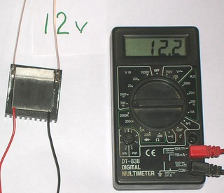
Let's again calculate the calibration coefficient.
Applied power W=U*U/R=12v*12v/2000 Ohm = 72 mW
(R=2000 Ohm is the resistance of calibrator in our case)
Calibration coefficient k=W/(readings – zero value) = 72/(12.2-0.5)=6.15 mW/mV
It is almost coincident with what we got earlier. A good sign. It means that there is no mistake and the gauge characteristic is linear at least up to 72 mW.
- If Your power supply supports other voltages You surely can add more measurement points onto the calibration curve. (Be careful at higher powers – the resistors may become overheated and unsold or unglued. The foam plastic covering may be damaged too.) As the experience shows the calibration of this sensor is almost linear up to 2-3W. Further it begins to saturate. For higher powers You need larger Peltier module, larger heat-sink and more powerful resistors for calibrator. The same idea but larger scale.
The calibration coefficient is found. Now the sensor is ready for measurements. One more note: if seeking for higher precision one should make 5 or more calibration points and calculate calibration line by method of least squares (any technical college teach how to do that). For example a computer power supply can also provide 24 volts (between yellow and blue wires) and 17 volts (between blue and red).
IV. The measurements.
↑
- Make sure that calibrator is switched off. Just in case.
Switch on the multimeter (200 mV range) and wait for readings to settle.
As usual write down the zero value.
- For this example I have selected a laser pointer as a laser to be measured. Then light with the laser pointer onto a working surface of the sensor (the blackened surface of the Peltier element). Wait for readings to settle. With laser pointers typically the readings slowly go up to maximum and then slowly fall down (the batteries output becomes lower when they are used for a rather long time). It is handy to fix the laser pointer someway (a clamp, duct tape, mounting). Also it is not desirable to stare at the laser spot – or else you will catch rainbows in eyes. For a mains powered laser pointer write down the settled readings, for the battery on take maximum readings.
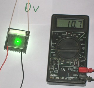
- Recalculate readings in millivolts to power in milliwatts:
Laser pointer power w=k*(readings – zero value) = 6 mW/mV*(10.7-0.0) = 64 mW.
k – is the calibration coefficient that was found out during the calibration process.
V. Comments.
↑
Primitive. But easy and effective.
The 'skilled in the art' may replace the multimeter with a small board with a ADC chip and microcontroller (PIC or Atmega), organize USB interface, write some code for auto calibration, error analysis, and… and… sell it for 1000 USD as a professional device.
The main errors are due to drift of zero value. On the photos You can see the drift of about 0.5 mW that corresponds to 3 mW. That means You can sense the 5 mW laser pointer but You can't measure it. The error would be too high. Zero drift is mostly due to draughts. When calibrating and measuring "close all windows" and doors too. And try to not disturb the air without a very necessity. If You fail to stabilize readings – measure the zero drift amplitude (subtract minimal zero readings from maximal ones) and treat it as additional measurements error.
Also it happens that multimeter sensitivity does float. Especially if this is a cheap one. Here You will need to redo the calibration (part III). Yes we all are lazy ones, but You really need to recalibrate after the multimeter battery was changed, after heavy weather changes, after each renew of blackening layer on the Peltier module… and simply from time to time.
If the measurements are made not by 'lazy shortened' version but on the contrary – with calibration, zero settling, and double or triple repeat with subsequent averaging, then measured power will differ from the one been measured with a high grade professional device less than by 10..15%. Needless to say that if You have a professional device You may also measure the bias due to non 100% absorption by the blackened surface. However with good blackening this correction is really small.
If the toad does not suffocate, You may expend some more money for a second Peltier element and connect both into a balance scheme (e.g. the bridge scheme). Then if mounted on the same heat sink one of the elements can be measurer and the other is compensator. It will help much in struggle with draughts. However it is rather hard to find a good pair of elements. In fact we usually deal with a low quality Peltier elements having a number of microcracks inside their crystals. These microcracks cause different internal resistance and voltage losses and their number and influence are random. In order to get a good pair of Peltier modules with the same parameters You either have to buy expensive high quality modules or need to search thoroughly through quite a number of them. Of course digital technique of data processing can save situation even for two random modules, but this approach from no point does resemble making simple handy device in 5 minutes.
If we assume that all silicon columns in the Peltier element are similar (and this is true due to the fact they are machine made) then the readings of the measures are independent of the position of laser spot on working area. Indeed: thermal voltage of each column is  , where , where  – is a specific thermal voltage of this column, – is a specific thermal voltage of this column,  – thermal drop on this column. Then – thermal drop on this column. Then  , where , where  – thermal resistance of the column, – thermal resistance of the column,  – amount of heat (power) coming through this column. What we are measuring is the sum of all voltages: – amount of heat (power) coming through this column. What we are measuring is the sum of all voltages:

Here the assumption of equality of all columns goes: if  and and  then then

So whatever the distribution of wi is the Umeasured is proportional the total heat power W going through the Peltier module. Of course (see note above) in real case things are not so good due to the fact that columns are not so similar to each other, but here helps the ceramic top of the Peltier module that has high thermal conductivity and equalizes the heat distribution. In practice there was not ever noted any dependence of the sensor's calibration coefficient to the position of ray spot. (In limits of measurements errors of course.)
For blackening of the working area one should never try to use inks, markers, pens and so on. Generally one should avoid any paints except ones based on graphite or soot. The root of evil is in the fact that most dyes have spectral selectivity – You may sense the ink as black, but exactly at the wavelength of Your laser it may have very low absorption.
The last note at last. With this device You can discover many unusual things about Your favorite lasers. You should be ready to accept them. For example You may find that 1 W rated diode laser emits only 600 mW in its beam. And other 400 mW (and often more) goes as diffuse halo (being not captured and focused by lense). You may find that DVD drive diode that eats 300 mA (and so You thought it to emit 300 mW) gives only 160 mW and on remaining voltage it hoots. (Note that when carefully focused it takes only 50..60 mW to burn a match.) The other exciting discoveries are left to be done Yourself.
<< HOME PAGE |


