1. The Introduction.
Solid State laser is a curious specie. It was the first to be discovered
among all lasers. But then they discovered many other lasers, that have higher
efficiency, higher average power and more usefull wavelengthes. The beam
divergency of the solid state laser is a bit better than one of semiconductor
lasers or liquid ones, but worse than one for most gas lasers or fiber lasers.
Neither price nor the simplicity of the design do distinguish the solid
state lasers in a positive sense. (Yes if You already have laser crystal and
laser lamp, it is very simple to put them together and wrap with an aluminium
foil. But the crystal need to be grown and processed, and a good laser lamp
is not simplier than a gas laser tube.)
And nevertheless neither type of lasers was able to squeeze the SSL's out.
Why are they so usefull? Because solid state laser is the most direct way to
get very short and powerfull pulses of light. Such pulses are often called as "giant pulses" and the process of their production is called "q-switching".
Due to comparatively long lifetime of the upper laser level and due to the
absence of bottlenecks in the pumping mechanism the solid state lasers are
of "accumulative" type. It means that if one forces the laser not to light
before certain time, the energy can be accumulated in the laser material and
then, when one lets the laser to oscillate, it can be emitted during a very
short time. 10..20 nanoseconds usually.
What it gives? So powerfull light is easy to be transformed into light of
other wavelength. E.g. http://www.milankarakas.org/pub/KDP/HomegrownKDP.html teaches how to use a
homegrown crystal to transform the invisible light of neodymium laser into
well visible green light.
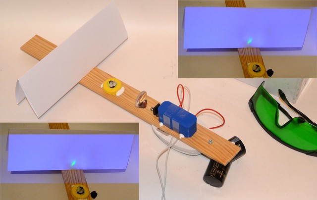
When focused the powerfull laser pulse can damage
a completely transparent glass - this phenomena is used for 3D-drawing inside
transparent blocks of glass. And, yes, the laser spark, we all love so much,
does also require short and powerfull laser pulses.
A megawatt solid state laser is a small device (1 MW=20mJ/20ns) consisting
of a laser rod as small as a thin pencil, a lamp of the same size, a q-switch
and a frame with resonator mirrors. Its power supply allows to use of
electrolytic capacitors and therefore can be small too. The key elemrnt for
obtaining the high power is the q-switch. Until a certain moment of time it
keeps the resonator closed by preventing the light from free travelling between
mirrors. And then it opens instantly, giving the way for the avalanche like
process of light amplification.
The q-switches can be of passive and active types.
Active q-switches are actuated by external controlling force. Mainly they
can be electrooptical, mechanical and acoustooptical. The mechanical ones
(with rotating mirror or prism) require exotic high speed motors with soft
motion. Acustoopitcal ones require very complicated control circuits. Control
circuits for the electrooptical q-switches are significantly simplier, but
switches of that type utilize effect of polarization rotation and the laser
requires a polarizer to be installed into the resonator. The polarizer has to be resistant to optical damage and has to be designed for the desired wavelength. It is rather strange but one can easily find a Pockel cell on the <e6@y> (Hard to say that it is cheap, but still obtainable.) but almost no chances to get the needed polarizers there. There also exist q-switches utilizing the effect of broken full internal reflection. However their production requires fine fitting of the optical parts together - the procedure You most probably want to avoid.
For DIYer it is simplier to make a passive q-switch. That one opens itself
when the light in resonator begins to build up (e.g. when a weak free running oscillation starts). Passive q-switches are usually made of the so called phototropic materials, the ones, where transparency grows with the intensity of accidental light. It may be some dyes, certain semiconductors, doped glasses or crystals.
Passive Q-switching dyes are rare. The ones used for ruby laser they are at
least humanly named - e.g. chloroaluminium phtalocyanine. Dyes for q-switching
of neodymium lasers are mainly known only by their numbers.
Among solid media for ruby laser q-switching there exists a KS-19 glass and
for neodymium laser there exists aluminium-yttrium garnet doped by four valent
chromium. Those are well known for professionals but still are hard to obtain
for DIYer.
Is there something more affordable?
Yes. It was found out that there exist a few schemes of q-switching that can
be build completelely with readily obtainable materials. In the first order
these are resonators which change their losses by changing their stability
factor (bases on self-focusing phenomenon), resonators that change losses due
to wafefront reversal reflection and one more interesting scheme based on a
phenomenon of restored full internal reflection. Moreover it was found out that
for ruby laser a common medical antiseptic dye "brilliant green" can be used
for q-switching with a certain success. But let's discuss it successively.
2. The Testing Lasers.
a) Ruby laser.
The laser is assembled with the use of semielliptic pump cavity of an old
commercial laser. Ruby rod has 6 mm diameter and 75 mm length. It is a pink
ruby. The lamp is FXQ-1302, xenon filled, with a silica tube having 4 mm inner
diameter, 6 mm outer diameter and 75 mm of spacing between its electrodes.
The pump cavity is placed into a resonator formed by two flat dielectric
mirrors obtained from a DVD-writer head. A mirror that has neglible transmission
in red spectrum was choosen as the back one, and mirror having about 30%
transmission in red was taken as a front one.
The lamp is fed by a homemade power supply based on six electrolytic
capacitors 1000 mcf x 450V, connected into series-parallel circuit that has
total capacity of 1500 mcf. The feeding circuit is shown on fig 2.1.

Fig 2.1. Ruby laser feeding circuit. Transformer Tr1 is a commercial
flashlamp ignition transformer. An alternative can be wound on a ferrite
rod having 6 mm diameter, 30 mm length and magnetic permeability of 400.
The secondary winding in this case should contain 360 turns of enameled
0.1 mm wire in 3 layers with strong insulation between them. The primary
is to be wound above the secondary and contain 4 turns of wire. The SG1
is a surge arrestor spark gap of NSR or GDT type having the triggering
voltage of 470 volt. One can use a discharger with other triggering
voltage, but it requires recalculation of R5:R6 divider.
When the voltage on the storage bank reaches 770 Volt the spark gap SG1
triggers and ignites the flashlamp that pumps the laser. The charging voltage is limited by a sparg gap firing. However one can not increase it much higher due to huge leaking current of the electrolytic capacitors, which rises greatly when the voltage approaches to 400 volt per capacitor.
Therefore the energy accumulated up to the moment of flashlamp triggering
is 440 Joules. The design of laser is shown on fig 2.2. Flashtube ignition pulse is put directly onto the metal body of pump cavity.
In the free running mode (without Q-switching) the output energy reaches
about 1 Joule. It was measured by ancient laserists method - the number
of rathorblades that can be punched through by the focused beam is equal
to its energy in Joules.

Fig 2.2. Ruby laser. General view.
b) Neodymium Doped Garnet Laser.
There is used a crystal of aluminium-yttrium garnet doped by neodimium
(YAG:Nd) that has 8 mm diameter and 110 mm length. The flashlamp is an
aviation signal strobe tube that has already been described at this site
in a section devoted to the dye lasers. The flashlamp is xenon filled and
has 8 mm bore, 10 mm outer diameter and 110 mm between its electrodes.
The pump cavity is totally homemade - the lamp and rod are wrapped together
by polished thick copper foil. In principle one can obtain a working laser
using the common kitchen aluminium foil but it is lousy way. The aluminium
foil of common (up to 14 mcm) thickness becomes broken into pieces and
dust after several flashes of lamp. From the outside it looks like gradual
and mystifying drop of output energy from pulse to pulse.
The back mirror has dielectric coating with reflection over 90% at 1064 nm.
Mirrors of that kind are easy to obtain over the internet. The output coupler
is formed by two microscope coverslips, having been put together and glued
by a glue-gun (thermal glue) over their perimeter.
The feeding circuit is similar to the one of the ruby laser (see fig 2.1)
but uses a single paper metal KBG-M capacitor instead of a bank of electrolytic
ones. It has 100 mcf x 2000 V value. Charging voltage is also 2 kv. Flashtube
ignition pulse can be put directly onto the wrapping foil of the pump cavity.
The laser crystal being used has wedged ends and grinded side surface.
It gives additional losses and makes the alignment more difficult but it allows
to accumulate more energy on the upper laser level without starting of lasing
on the reflections from the rod's ends. Moreover the rod has plenty of narrow
scratches (hair-thin-scratches) on one of its faces, but it does not prevent
lasing and does not provoke an optical damage at the obtained power levels.
The length of the resonator is 45 cm, that makes the laser to be not as small
as it could be, but allows to torture the resonator by inserting lenses,
filters, cuvettes and pinholes of any kind. The photo of the laser is shown
on fig 2.3.

Fig 2.3. Neodymium Doped Garnet Laser. General view.

Fig 2.4. The power supply circuit of the neodymium laser. Parameters of transformer Tr1 and spark gap SG1 are similar to those shown on Fig. 2.1.
3. Observing of the Q-Switching effect.
The most direct way to obtain information, that allows to say that q-swithing has taken place - is to use a fast photodiode and oscillosope. If the reverse
value of the oscilloscope's passband width is small when compared to the
expected duration of pusle, one can register the time shape of the pulse
and measure its width. If not - one can only register the fact of presence of
a peak that has width less than the resolution of the oscilloscope.
For example for measrements of width of a 20 ns pulse, one needs a device
with 150 MHz bandwidth. But if it is only needed to detect the fact of the
giant pulse appearing, one can use an oscilloscope with bandwidth of a few
megahertz. Because the usefull signal is single (or repeating with a very long period) one needs to have a storage type oscilloscope. Or a digital one. In the last
case one needs to pay attention not only to the bandwidth, but also to the
sampling rate, that is usually measured in gigasamples per second (GSa/s) or
in megasamples per second (MSa/s). The interval of time between the samples (the reverse value of the sampling rate) should also be at least several times less than the durations of processes that You want to observe. To measure the width of the giant pulse it will take not less than 200 MSa/s. If You only want to detect the pulse, You will need only several MSa/s.
An oscilloscope fast enough to resolve the shape of giant pulse is a piece of rare and expensive equipment. DIYer usually can not afford such a device.
Therefore let's assume that this method allows only to detect the fact of
the giant pulse presence and to calculate the number of the giant pulses
having been produced during one flashtube burst. (Differently from the lasers
with active q-switching, the ones with passive q-switching do often produce
several pulses in one burst. And the higher is number of pulses the worse.
Because each pulse has lowe peak power.) During that kind of measurements one
can barely bother about saturation - overloading the photodiode and driving
it deep into area of non-linearity. Fig 3.1. shows how to use the photodiode.

Fig 3.1. The sample circuit that shows photodiode usage for measurements.
R1 and C3 should be connected as close to the photodiode as possible. C3
is a ceramic disc type or SMD type capacitor. R1 - is metal plated resistor.
Both should be low ESL type. C2 is ceramic high frequency capacitor. C1 can
be electrolytic. The connection to the oscilloscope should be made by a
coaxial cable having characteristic impedance of 50 Ohm. If there's no risk
of long powerfull light exposure of the photodiode the R2 resistor may be
absent. In this case connect the batterry directly to the buffer capacitors.
The second widely known (but almost not described in literature) method
is registration of the laser spot on the surface of silver-halide photomaterial.
It can be photofilm, photoplate or photopaper. The photomaterial should be
exposured but not developed. It also needs the laser wavelength be longer than the passport red border of the photomaterial. Otherwise it
will be hard to distinguish giant pulse from free running mode.
The method is based on multi-photon absorption in high intensity laser radiation. It gives the similar blackening as it would be if the material was exposured with the light having its wavelength shorter than it is in the reality. Most black-and-white photomaterials are sensitive in blue-green
range of spectrum, so they are suitable for registration of neodymium and
ruby laser spots. Green and blue lasers blacken the photoemulsion effectively
even in continious wave mode. On the other hand TEA CO2-laser does not provide
blackening of the photomaterial even when the power is so high that its surface
is fully covered by bright laser plasma. Some color films have sensitivity
range that covers 694nm. That ones blacken under the free running ruby laser
spot.
Usually it is not difficult to recognize the spot of giant on an exposured and undeveloped photomaterial. The free running laser radiation
either does not produce black spot at all, or (at high energy densities)
gives burned and/or flowed surface. Q-switched laser radiation at moderate
energy densities gives nice print in the form of blackened spot without
any traces of burning or melting. At high energy densities the traces of
burning will certainly appear, but in doubtfull cases it can be resolved
by reduction of energy load on the photomaterial. For example place the
film further apart from the laser, where the spot will be wider due to
the natural divergency. Fig 3.2 shows an example of blackened spots on
a photofilm produced by q-switched neodymium laser.
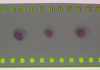
Fig 3.2. Beam spots on a photofilm produced by the q-switched neodymium
laser.
The method is easy and effective. It allows user to quickly understand whether the giant pulse comes out from the laser or not. It also allows to make a rude estimations of output energy.
However this method will never give You an idea that instead of a single pulse Your laser produces several ones per burst, and exactly due to this very fact You can not obtain the laser spark even when the total energy is significant.
Besides, the victorious spreading of digital photo makes it more and more difficult to obtain silver-halide photomaterials.
It can reach that point when it will become actual to make a guide for
making photoplates at home.
Another pair of usefull phenomena is air breakdown and dielectric breakdown.
If You observe a laser spark in the focused beam of Your laser, it is
obvious, that q-switching has taken place. According to [1] the breakdown
of the air at athmospheric pressure under laser radiation having wavelength
of about 1 mcm takes place when the power density is above w0=300GW/sq.cm.
If You have nothing against high errors, it allows to estimate the output power W of Your laser:
W=3e11*3.14*(theta*f)^2/4 [Watts]
theta is the divergency of Your laser taken in radians, f - is a focal length
of the focusing lense taken in centimeters.
For example, lets assume that the beam diverges by 1mm at 1 meter. It means that the divergency is 1 mrad. And lets take that the laser gives sparks when used with lense having 1 cm focal length. Then:
W=3e11*3.14*(1e-3*1)^2/4=235 kW
If we take that the pulse duration was 10 ns, the output energy appears to
be as little as 235kW*10ns=2.35 mJ.
If Your laser beam was focused into a transparent glass brick and left there
a trace in the form of white star of optical damage, one can say that the power
level is high enough to state that q-switchng has definitely taken place.
However for the quantitive estimation this method is of low use. Because the damaging intensity varies greatly dependently on the glass type and quality. One
should keep in mind that organic glasses and transparent plastics can easily
be broken inside their volume by radiation of a free running laser. So
these materials arent suitable for these tests.
4. Q-Switching Based on Self-focusing
Scheme of the q-switch is shown on the figure 4.1.

Fig 4.1. Scheme of the q-switch based on the intracavity self focusing.
1 - back mirror of the resonator, 2 - tightly sealed cuvette, 3 - working
liquid, 4 - pump cavity with lamp and laser rod, 5 - output coupler,
6 - lense, 7 - lense.
Similar scheme was earlier published in article [2], where, as usual, only the idea of the scheme wass given, and only brief description of the best results was done. All troublewatching details are omitted as expected. It was only said there, that when the lenses were placed correspondently to the high lasing threshold, the
q-switching process took place. And when lenses were set for the low lasing threshold, there was no q-switching effect. Another fact from that work is that after a few tens of pulses the cuvette was destructed. Neither there exist any details how to select that position of the lenses, "correspondent to high threshold" and good
q-switching, nor any information about the alignment difficulties. Another similar scheme was implemented in work [3],
but its authors state that the main phenomenon causing the q-switching is a dynamic reflecting hologram in liguid, or in other words: "SBS mirror". This article also contains no information on stability of the effect
or alignment difficulties.
A set of cuvettes was made, that have lenses as their end walls. This design was choosen to avoid the risk of optical damage of a glass wall near the narrow place of the beam. And really, during the experiments (more than a hundreed
of pulses with each cuvette) no damage was observed. The cuvettes have(d)
magnification ratio of 1:1 i.e. front and back lenses have the same focal
length. The focal lengthes were the next:
- Cuvette #1 f1=f2=14mm
- Cuvette #2 f1=f2=23mm
- Cuvette #3 f1=f2=74mm
It should be specially noted, that the focal length was measured from the side of liquid, when one side of the lense was surrounded by air and the other side was surrounded by isopropanol. When dry or fully drown into liquid the lenses would have completely different focal lengthes.
Isopropyl alcohol and petrol were used as working liquids. Water was also
tried out but without any noticeable q-switching.
Some successfully working q-switches were made of cuvettes with fixed spacing between lenses, but it required too high precision of material processing, especially for short FL lenses. Better results
were obtained when the cuvettes consisted of two threaded parts (tubes) screwed
one into another. It made it possible to adjust the spacing between lenses.
The thread connections were made tight by addition of a fluoroplastic ribbon.
Small cuvettes are robust to be made of parts of ballpoint pen bodies. Larger cuvettes were made using sewer/water pipes and fittings.
Lenses were glued by thermal glue (glue gun, black colored rod) for the cuvetters intended for isopropanol and by epoxy caulk for the cuvettes intended for petrol.
WARNING! THE LIQUIDS USED ARE FLAMMABLE! Laser beam can heat things to ignition. Poorly designed power supply can produce sparks. Be carefull and observe preventive fire fighting regulations. Keep the cuvettes sealed tightly. Avoid leaks of liquid. Take care for proper laser beam position. Avoid hitting the cuvette body by the main and parasitic laser beams. It is a good rule too keep the main stock of the working liquid away from the place of experiments.
Photos of the complete cuvettes are shown on fig 4.2. Photos of lasers with the cuvettes in their resonators are shown on fig 4.3.
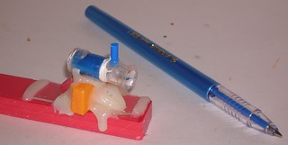

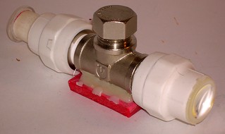
Fig 4.2. Cuvettes for intracavity self focusig q-switching.
a) Cuvette#1, b) Cuvette#2, c) Cuvette#3.

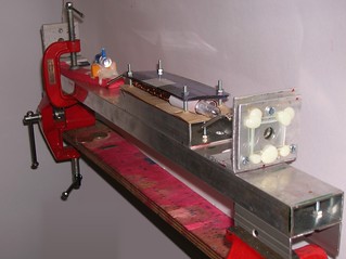

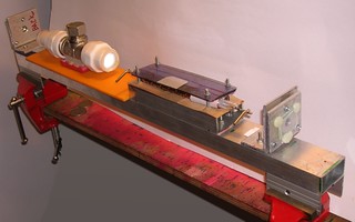
Fig 4.3. Lasers with the cuvettes having been installed.
a) Ruby laser with cuvette#1. b) Neodymium laser with cuvette#1,
b) Neodymium laser with cuvette#2, b) Neodymium laser with cuvette#3.
The procedure of alignment of a laser with intracavity cuvette does not
practically differ from the common procedure of aligning (of a plano
parallel resonator). An auxiliary laser (helium-neon one or laser pointer)
is placed in meter or two from the laser being aligned, and then spots of
beams reflected by the front and rear mirrors are to be moved to overlap the
aperture of the alignment laser (the detailed description of this procedure can
be found here on this site in the guide on the longtitudinal pulsed carbon
dioxide laser). Because cuvette inverts image the beam reaction on the rear mirror motion becomes inverted. It is somewhat uncommon but does not
make serious difficulties.
When the cuvette is set to the parallel beam (by adjustment of space between lenses) the sensitivity of the laser to misalignment stays at the
same level as for cuvetteless laser (misalignment of ±3mrad does not cause lasing to cease). Setting the cuvette to convergent beam makes the
cavity to be stable and reduces sensitivity to misalignment. Setting the
cuvette to the divergent beam makes the cavity to be unstable and increases
the sensitivity to misalignments. When the cuvette is set to divergent beam
and gives about 20 mrad of divergency (full angle) it is about to be
a limit, when the laser can still be barely aligned with existing precision of mirror mounts.
Q-switching was obtained with all three kinds of cuvette settings: to
divergent beam, to convergent beam and to parallel beam. The best results
(best energy and beam quality) were obtained at parallel beam setting.
The adjustment to the parallel beam can be done in the next way.
The beam of the alignment laser should be directed to a screen (door or
wall or any suitable place). The screen should be far enough from the
alignment laser - preferrably over 1.5 meters. Using a pencil or marker draw a circle around perimeter of the spot of the alignment laser beam on
the screen. The next step is to put the cuvette onto the beam and align it so that the center of the spot, given by the beam that comes out of the cuvette, to be near the center of the pencil drawn circle. Then adjust the spacing between lenses (if needed correct the angular alignment of the cuvette) to inscribe the beam spot into the pencil drawn circle. When it is done the cuvette is correctly adjusted to the parallel beam, and it is ready to be installed into the laser cavity. (Of course all the adjustments You are to make with the cuvette being already filled with the liquid.)
Results obtained with the neodymium laser are the next. Laser usually gives train of pulses. Each pulse is 50..100 ns. The duration of the train is the same as duration free running pulse. Number of pulses in train is usually 10..15
and gets lower when:
- when choosing longer cuvette
- when front or back resonator mirror is misaligned
- when the cuvette is set to highly diverging beam
However when approaching to single pulse mode the energy drops seriously
(to ~1 mj). Therefore if You are more interested in total energy of pulse train,
(as e.g. when trying to mark a glass in its volume) most probably it is not a good idea to pursue the single pulse.
When filled with the same liquid it appears that longer cuvettes tend to
produce longer pulse. When the cuvette and liquid are fixed, the shortest pulse (<20ns) can be obtained when the cuvette is adjusted to strongly convergent beam (when the resonator becomes unstable again). The lasing in this case has
low reproductivity - energy is low, duration and direction of beam vary from
pulse to pulse (the spot "jumps" from position to position). Longer pulses
(~30..50ns) can be obtained when the cuvette is set to moderately diverging beam. But
the beam quality and lasing stability are better. Even longer pulses (~50..100ns) are produced when the cuvette is set to parallel or slightly
converging beam. The lasing is most stable here, the spot is uniform and
the pulse duration shows minor changes fom pulse to pulse. The output energy
in this mode is maximal.
Need to note that the shortest registered pulse duration (20ns) is defined
by the oscillograph resolution and most probably the pulses were even shorter.
The top obtained energy was ~60 mj in a train with 15 pulses. Each pulse had
duration ~50 ns. I.e. average energy per pulse was 4 mj, power per pulse was
~80 kW.
Typical oscillosocpe traces of pulses of neodymium laser with cuvette#2 are
shown on fig 4.4. Laser spots captured by undeveloped photofilm are given
on fig 4.5. Fig 4.6 shows the photos of optical damages having been obtained when the beam of neodymium laser with cuvette#2 was focused into a
glass volume by lense with 10 mm focal length.
 

Fig 4.4. Traces of typical pulse of the neodymium laser with q-switching
based on the intracavity self-focusing. a) The whole train of pulses, timescale
is 10 mcs per cell.
b) one pulse from the train, timescale is 100ns per cell.
c) Free run mode without q-switching, timescale
is 20 mcs per cell.

Fig 4.5. Spots of neodymium laser with cuvette#2 (set to parallel beam)
captured by an undeveloped photofilm.


Fig 4.6. Optical damages in a glass volume, obtained with the use of
the neodymium laser q-switched by cuvette#2.
The cuvettes were also tested in ruby laser. The prominent q-switching
was observed, but the output energy and power were sufficiently lower than ones
of the neodymium laser. Typical oscilloscope traces of pulses produced by the
ruby laser with cuvette#1 are given on fig 4.7. Spots on undeveloped film
are on fig 4.8.
 

Fig 4.7. Oscilloscope traces of pulse of the ruby laser being q-switched
by intracavity self-focusing.
a) The whole train of pulses, timescale is
50 mcs per grid cell.
b) One pulse from the train, timescale is 500 ns per
cell.
c) Free run mode without q-switching, timescale
is 100 mcs per cell.
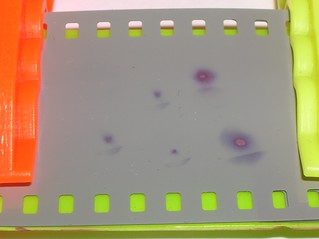
Fig 4.8. Spots of the ruby laser q-switched by cuvette#1 on an undeveloped
photofilm. The cuvette was adjusted to parallel beam.
Conclusion. the q-switch based on the intracavity self-focusing can be made
of readily available resources, it is simple in production and tuning, gives
stable but not very high results. It is good that this q-switch can be used
for neodymium laser being known by rarity of saturable absorbers suitable for
its modulation. The q-switch is acceptable for low gain lasers, it was approved
by tests with ruby one. The most difficulties may appear at a stage of getting
suitable lenses. But this question is solvable. At least one can buy and
dismantle a pair of old second hand photocameras. A good choice for an amateur
but dont expect much from it.
5. Q-Switching Based on the Regained Full Internal Reflection.
In work [4] there was described another design of passive optical switch for laser q-switching. It was basesd on the phenomena of regaining of the full
internal reflection (RFIR). An essense is that a prism is installed into the
resonator, and its reflecting face is in contact with a liquid that has decent
absorption at the working wavelength. The prism is installed in such a position
that the full internal reflection is still not reached on the border of the
glass and liquid. When the system begins to lase the liquid boils and recovers the full internal reflection. The reflection at the working face of the
prism grows fast and q-switching takes place. (I intentially simplify the
process in order for easier understanding. In [4] much more complicated working
cycle of this q-switch was described. It includes variation of the refraction
of the liquid with heating and relaxation of liquid density by means of
acoustic waves). The proposed in [4] schematics of the q-switch is shown on
fig 5.1.

Fig 5.1. Scheme of q-switch based on the regained full internal reflection
1 - output coupler. 2 - pumping cavity with lamp and laser rod, 3 - the
cuvette, 4 - working liquid, 5 - rear mirror, 6 - prism.
Even a brief analysis of figure 5.1 shows that huge problems with alignment
are expected. When the prism is placed at such an angle to the resonator
optical axis that full internal reflection does take place, it appears that
there is no q-switching. And when there is no full internal reflection and
the angle is far from critical, the resonator has too high losses. Even if
the reflection of the output coupler is close to 100% in order to compensate
that losses the active medium of the laser is to have gain of about 1/ro per
pass, where the ro is the reflectance on the border between glass and liquid.
When far from the critical angle it is small and one can expect ro~1..5%. It
corresponds to gains of 20..100 per pass - very high gain even for laser based
on YAG:Nd crystal. The ruby and neodymium glass are far from that.
In the original work the authors offer to solve that problem by settenig
the prism at an angle very close to the critical one. Here ro has higher values and depends strongly on the angle (it varies in range from a few percent to
100% in less than a degree). Exactly that point of (a very) unstable
equilibrium is offered to balance at. On the one side we should provide absence
of the full internal reflection and on the other side we should keep the
reflection high enough for the laser to be able to start. The prim is to be set
with a precision up to few angular minutes, and moreover the rear mirror is to
be aligned properly to the jogged beam. It is aggravated by the fact that due to the dispersion of refraction, visible alignment laser does not provide any feeling how close to the critical angle the prism is set. In order to
avoid those difficulties a modified scheme was used (see fig 5.2)

Fig 5.3. Variants of q-switch schemes based on the regained full internal reflection. 1 - output coupler, 2 - pumping cavity with lamp and laser rod, 3 - prism, 4 - the
cuvette, 5 - working liquid, 6 - support auxiliary mirror.
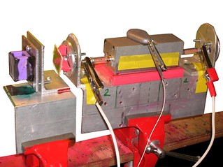
Fig 5.3. The ruby laser with the RFIR q-switch installed.
It should be said here that no liquid from those been tested (different
black and blue paints and dyes in different solvents and also a saturated
solution of copper sulfate in water were checked) has demonstrated sufficient
absorption at 1064 nm wavelength (it is desirable to have half apsorption in
10 mcm thick layer; poor but usable - half absorption in 0.1 mm layer). So
the RFIR switch designed accordingly to schemes 5.2a-5.2c was tested mainly
in the ruby laser.
Scheme shown on fig 5.2a was test one. As it had been expected neither ruby nor even neodymium laser has reached the threshold with this design of resonator.
Naturally when there's no lasing, it's nonsense is to speak on any q-switching.
For getting the initial lasing an additional semitransparent mirror was installed into the resonator (item 6 on fig 5.2b). It consisted of two
plano-parallel glass plates for the neodymium laser and of three ones for the
ruby. With such a reflectance the lasers were close to the threshold. It was a bit disappointing that despite the prominent initial lasing there was no q-switching when scheme 5.2b was used. The liquid in the cuvette remained
still during the laser pulse and it is probably the evidence of the fact that
it does not boil. Apparently the energy of startling lasing was insufficient
for heating the liquid to the necessary temperature.
In order to increase the energy density on the liquid's surface the cuvette
was filled up to the central edge of the prism or slightly below it (see fig.
5.2c). With this scheme the ruby laser has demonstrated prominent q-switching.
However this q-switch appeared to be of single use - after each pulse the upper
face of the prism was spit by the liquid and one was to perform its cleaning
prior to obtaining the next pulse. An ink from SCHNEIDER black permanent marker
diluted 1:1 with acetone was used.
Under the same conditions there was no q-switching in neodymium laser. It
appeared to be due to insufficient absorption in the solution - the less
absorption is the thicker layer of the liquid is being heated. And the more
energy is necessary to be deposited in order to heat it up to the necessary
temperature.
For increasement of the startling lasing energy the reflectance of the
intracavity auxiliary mirror was increased. Additional glass plate was installed into neodimium and ruby lasers. As the result the q-switching
did not appear in the neodymium laser and disappeared in the ruby laser.
I.e. when the reflectance of the auxiliary mirror is too high the q-switching vanishes.
Despite of the fact that spitting of the solution makes bad feeling, there was no visible damage on the prism faces after several tenth of shots.

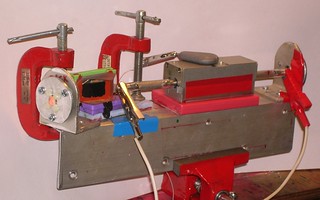

There alse were done tests with the direct scheme proposed by authors (see photos above). As it was expected the alignment process was hard and sophisticated. And the stability of my mirror mounts was barely enough for the laser to keep the q-switching mode within less than 15 minutes. The results however were the best.
CONCLUSION: RFIR q-switch works, but in its original design it is very
clitical to the alignment. Its modified design requires usage of easy
boiling liquids with high absorption at working wavelength. The energy losses
are high (estimations give ~500mj/sq.cm even for acetone based solutions)
but even with that the output of laser with RFIR q-switch outperforms the
one with intracavity self-focusing q-switch.
6. Brilliant Green as a Q-switching Dye for Ruby Laser.
In work [5] it was noted that under the pumping by ruby laser there was
obtained lasing of such a popular dye as brilliant green. And its lasing
wavelength (755nm) was pretty close to the one of chloroaluminium phtalocyanine
(759nm). The last is used widely for q-switching of ruby lasers. Dye laser
of such a wavelength is of low interest (at least for DIYer) but the possibility
of making the q-switch for ruby laser is intriguing. Especially if one
remembers that that dye is used widely in medicine as a desinfection aid
(Fig 6.1).
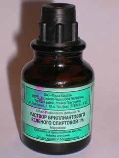
Fig 6.1. The well known medical desinfection aid - 1% solution of brilliant green dye in ethanol - appears to be capable to make q-switching in ruby lasers.
Cuvette with brilliant green was installed into the ruby laser's resonator
and, after minor work on concentration adjustment, the result became visible by
the naked eye - it burned out the rear mirror. The cuvette was commercial
plano-parallel glass cuvette from spectrophotometer. The dye was dissolved
in isopropanol. - To a clean isopropanol the medical solution of brilliant
green (1%) was added by microdrops until quenching of lasing. Then the solution
was diluted 1:1 with clean isopropanol.
Need to say that tests with brilliant green solutions were made with water,
acetone, glycerol and ethanol. But the prominent evidence of q-switching was only with isopropanol. The photo of the laser with the cuvette installed into
resonator is shown on fig 6.2. Oscilloscope traces of the laser pulses are
on fig 6.3. And on fig 6.4. there are snapshots of laser spots on undeveloped
photofilm.

Fig 6.2. Photo of the ruby laser with the cuvette with briilant green in
its resonator.
 

Fig 6.3. Traces of ruby laser pulses.
a) - free running mode,
b) - q-switching by brilliant green,
c) - One pulse from the train.
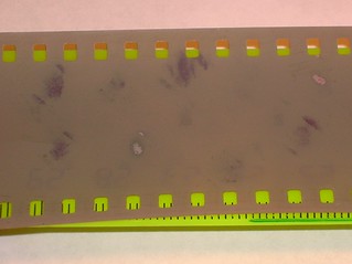
Fig 6.4. Photo of laser spots on undeveloped photofilm. Free running
lasing of the ruby is capable to blacken photofilm especially if it has
rather far red border of sensitivity, but the usual intensity, required for
it, causes melting of the photoemulsion. Here one can see clean blackened
spots without traces of melting.
From the comarison of the oscilloscope traces of lasing with and without
switching one can see that the number of peaks reduсes greatly, and intensity
in each peak becomes higher. The higher is the dye concentration, the less number of peaks is observed. However there is probably significant unsaturated
absorption that causes strong overall energy drop with increasing the dye
concentration. This laser was not able to give less than 10 peaks per flash
without ceasing of lasing.
Finally the surface of laser rod ends was damaged. The rod is from a q-switched laser, that means it should be light-durable. And the fact that its
endes were got down is a clear evdence of the fact that giant pulse was
produced. The photo of the damaged ruby rod ends is given on fig 6.5.
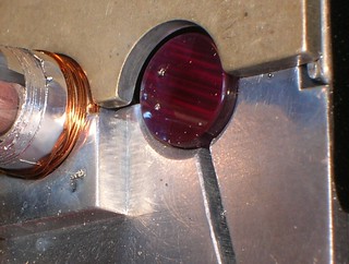
Fig 6.5. Ruby rod end surfaces damaged after lasing with brilliant green
solution in the resonator.
Addition, June 2020
Suddenly it occurred that a dye, known as "methylene blue" is available for DIYer. One should look for it in pet shop in a department of aquarium items. Ii is sold as an aid for aquarium desinfection there. I've got it in a form of 50 ml flask, containing 300 mg of dye and the rest is water.

The absorption spectrum of this dye matches almost perfectly with the emission line of ruby laser.

This match promises some good results, so I was to dig out my old ruby laser and restore it a bit. No sufficient modifications however. It is still the same MS-60 pumping cavity in a homemade resonator. Its native lamp has been expended long ago so its place is occupied by a Russian xenon lamp ISP-2500 now. The back mirror was replaced by a full reflective prism, because DVD mirrors aren't durable enough for Q-switched lasers. In addition the power supply unit of this laser was modified too. Its scheme remained unchanged in general, but a choke was added in series with the lamp at the side of its positive electrode. The choke was wound of 15 meters of copper wire in vynil insulation. The section of the wire was 2 square millimeters. The diameter of winding wad about 60 mm and it gave nearly 200 uH of inductance with ~0.1 Ohm of series resistance. The choke helps to prolong the pump pulse and allows the lamp to feel easier. It is its only goal. If You don't feel pity for the poor lamp, You can certainly omit the choke.

The solution of the methylene blue was prepared in two stages. At the first stage ~5 ml of some pure solvent (water, isopropanol or other) was poured into a separate vessel. Then two or three drops of aquarium methylene blue solution (300 mg of dye per 50 ml of water) were added to the solvent in the vessel. Thus an intermediate solution was made.
Then 4 ml of pure solvent were poured into a spectrophotometer cuvette (having the full volume of 5 ml). And then several droplets of the intermediate solution were added there. Three to five droplets were usually enough.
The results are the next.
Water as solvent. - There was no apparent q-switching.
Isopropanol as solvent. - Q-switching is observable but weak. A bit better than it was with brilliant green solution.
Glycerol as solvent. - Very prominent q-switching. The energy of q-switched burst is 20-50% of the energy of free running pulse. However oscilloscope traces show that the burst looks like a bunch of 20-50 peaks with total duration of 1.5 microseconds. Maybe it is a mode locking or something alike. The energy in each peak is low, so there are no "special effects". The laser is unable to make a spark in the air or to damage an inorganic glass even with sharp focusing. The glycerol was taken directly as it was sold in a drugstore. With no additional drying or purifying.
Dimethylsulfoxide as solvent. In Russia and Europe AFAIK it is very affordable for DIYers It can be bought in a drugstore as an aid for bolsters and applications. However beware that it may not be so easy to get in particularly country of Yours. In some countries it is treated as a hazardous substance. Check it Yourselves please. I've personally seen it on Amaz0n, being sold under the name "DMSO". If You were lucky to buy a pure DMSO or a concentrated transparent solution (conc.>70%) You may use it "as is". If You got a gel or an ointment You can try to vacuum distill or extract it out. If the gel is transparent enough, most probably You can still use it "as is". Just add the necessary amount of the dye and use.
Lets get back to the results. With DMSO as solvent it gave powerful q-switching. One could easily achieve a single pulse on oscilloscope trace. When there are 3 pulses, their sum energy was about 30% of the energy in free running mode.

"Special effects" were also present. The laser was still unable to ignite a free spark in the air, but it already could damage an inorganic glass. The damage spots are similar to ones given by neodymium laser with q-switch based on self focusing phenomenon>. The flame plume given by the beam on some target has got specific "electrical" color. Sometimes one can observe "a spark in smoke."


It was noted. however, that it degrades from pulse to pulse. Energy of modulated pulse diminishes and energy of the background free running grows. And it takes place already after two or three pulses. A droplet of vinegar essence (70% acetic acid) was added to the cuvette then. The quality of q-switching didn't degrade after that, but the stability but the stability became much better. Here are the spots on undeveloped photofilm:

All the spots were got one after another with pauses only for storage capacitor charging (12 sec). Not more than six pulses in one run - it is limited by overheat of ballast resistors in the power supply unit. With addition of vinegar to the dye in cuvette the q-switch became able to endure at least three such runs before notable degradation.
CONCLUSION: Saturable absorbers in the form of brilliant green dye solution
in isopropyl alcohol and in the form of methylene blue solution in DMSO are quite capable to cause q-switching of ruby laser.
For brilliant green lasing energy is, however, less than with a switch based on intracavity self
focusing. Probably it is due to poor choice of solvent or its acidity. On the other side methylene blue works even better than RFIR. Simplicity of the design and readily available materials
may make the shutters to be interesting for DIYers. And even if Your laser gives a series of pulses instead of single one it is insufficient when it is used in a MOPA
system, where the first pulse will deplete the energy stored in amplifiers
and the consequent pulses would be suppressed.
7. The Safety.
Q-Switched Solid State Lasers are very dangerous. In fact they can cause
severe injury to vision even by a beam reflected from any uncoated glass
plate (as low as 4% of the total energy!) at distances of several tenth of
meters.
Be extremely carefully! Get protection googles and use them! Remember the
rule of "cynic laserist": if You're in urgent need to see the action of the
laser radiation visually, use one eye only. The warriors of holy wars for
the safety will criticize that to ashes. And it is hard to not to agree with them - it is much better to hide the beam behind the wall, to dig it down to under the ground and not to watch it at any cost. But. If one ignores this and
needs to watch the laser spark or laser cut... What is better? To be one eyed,
or to be completely blind?
If You use the rule of cynic laserist - define what of Your eyes will be
in the group of risk, and always exploit only this eye. When damages are
minor the vision tends to degrade smoothly and it is better to have one
fully seeing eye than both half seeing.
And at the last. NEVER LOOK INTO THE LASER BEAM! Neither with safety
googles nor without them! When the energy got into the eye is high the damage may be so severe that may cause vision loss on BOTH EYES inspite the fact
that only one of them was damaged.
- N.I. Koroteev, I.L. Shumai. Physics of Powerfull Laser Radiation.
M., Nauka, 1991, 312 pages. ISBN 5-02-014474-6
- V.M. Kostyukov, N.T. Maksimova, Z.I. Myreeva. Modulation of Q-factor
of YAG:Nd Laser Resonator by Self-focusing in Water. in Proc. of
IV Russian Seminar-School "Luminiscence and Adjoint Phenomena",
Irkutsk, 1998. pp.212-214.
- V.I. Bezrodny, F.I. Ibragimov, V.I. Kislenko et al. On the Mechanism
of Laser Q-Switching by Intracavity Stimulated Scattering. in
Kvantovaya Electronica, 7, N3 (1980). pp 664-666.
- A.N Rubinov, I.M.Korda, E.A. Zinkevitch. Dynamics of Laser with
non-linear shutter on full internal reflection. in Kvantovaya
Electronica 32, N4 (2002) pp 319-323
- Dye lasers. under the edition of F.P. Schafer. Springer-Verlug Berlin-Heidelberg - New York, 1973.
<< HOME PAGE |


