Spark gap for 10..12 kV
"Lol, no problem. Let's take two wires, bend towards each other and KA-BOOM!" -
does think someone and certainly it is not correct. In most cases You won't be
satisfied with speed and losses of two-pin spark gap. And also the sound,
making neighbours to think about terrorism. And also the pins tend to burn out,
causing rise of the breakdown voltage...
For the braniac entertainments one need a more serious spark gap design.
In order to understand the essense of the design one should remember a Tappler law.
This law is certainly outdated and has been corrected many times by modern science,
but it is simple and allows to discover the sense. The Tappler law states that "Ohmic resistanse of the spark at the moment is in linear proportion to its length
and reversely proportional to the charge that have been flown through the spark up
to the moment t." I.e. R~l/Q(t). The spark resistance weakly depends to gas pressure
(when spark length is constant).
What's up with the spark resistance? Is it so bad? Yes, it is. First of all
the losses: we loose to heat a power that is equal to W=RI^2. (I - is the current
through the spark gap.) We also loose voltage on our load (on laser cell, or lamp,
or x-ray tube, or whatever else You want to connect to the spark gap). The voltage
drop will be dU=RI. The discharge time of all capacitors will rise (tau=RC) and
so on... It means that the lower spark length is, the better.
If we assume that voltage is given and unchangable, what can we do for spark
length reduction?
- To rise the gas pressure. (The brilliant way, and all serious spark gaps utilize
pressures of several bars. However the design will become larger and more
sophisticated. All things need to be hard and durable and vacuum tight. One also
need a compressor, pipes, fittings etc etc...)
- You also can replace the gas by one with higher dielectric strength (This is
a good way too. But where You will get the gas? SF6 is out of reach for DIY'er,
a freon appears not to be suitable - it decomposes with settling of carbon and
since that shortens the spark gap in a first few flashes... One also can try SO2,
but it is also complicated.)
- And one can flatten the electric field.
It's well known that the breakdown between pins in air appears at the field
density E=10 kv/cm, between balls at E=20 kv/cm, and when uniform field at
E=30 kv/cm. This means that flattening the field one can reduce the spark length
to half or one third. The spark resistance and inductanse will be lowered the
same order. Ideally the spark gap electrodes should have Rogovsky shape or
Chang's shape. It is rather hard to do, so let's limit our desires by a sphere.
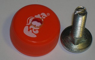
It appears to be suitable to use a furniture screw with a spherical head.
The other electrode can be flat. (We will use a piece of aluminium angle
having the side not less than 30 mm - to fit she spark gap's body).
The body of the spark gap will be a neck of a plastic bottle with its native
plastic lid. The body will be tight (that reduces noise) and also it can be
opened at any time for cleaning. All parts are shown on the next pictures.


Plastic body of the spark gap is attached to the aluminium wall by glue.
First time epoxy glues were used. However the result was unstable. Later it
appeared to be more reliable to use a thermo-glue ("glue-gun").
To make gluing secure drill a plurality of holes (2 mm diameter) around the
perimeter of future seal. During the gluing process the glue will flow into
the holes and will form a set of columns, which keep all parts together as
usually rivets do.

Cut the neck from the plastic bottle, flatten the cut place and glue it to
the aluminium angle. Just before the gluing process the aluminium angle is
good to be heated up to sixteen Celcium degrees (hot when touched). If glued
without heating the seal will be weaker and the spark gap will endure less
power.


At the center of the plastic lid drill carefully a hole with diameter by
0.5-1.0 mm less than the diameter of the screw thread. (If here we use
the M8 screw we should drill 7 mm hole.) Cut a slot on the threaded edge
of the screw. The slot should fit a large enough screwdriver. It will later
be used for spark gap adjustments.
Screw the screw into the hole in the plastic lid, as it's shown on the next figure.

The next step is to assemble the spark gap.

And to put it into the circuit where it will be used.

That's all folks.
After all, connect the spark gap to a multimeter having been set to resistance
(ohms) measurements, and screw down the spark gap screw until the multimeter
will detect the shortened circuit. Mark the zero position of the spark gap screw.
Later You will use it as zero point when setting up the required breakdown voltage.
What else one should know about apark gaps?
- Immediately after breakdown the spark gap has relatively low conductivity.
Ftom the Tappler law it follows that one need to push a considerable electric
charge through the spark gap ASAP after the breakdown. To heat the spark plasma.
In order to do this they connect a low inductance capacitor just in parallel
to the spark gap. (The so called "peaker" capacitor.) The peaker capacitor should
be connected with lowest possibble inductance and with shortest possible wiring.
- The spark has limited speed of growth (around ~1 mm per nanosecond), so the spark gap
has limited breakdown time. And the longer the spark is (the higher the operation
voltage is), the longer the switch time becomes. This is why an air spark gap
designed for, say, 30 kV voltage (sparklength is over 10 mm) can principally not
provide switch time less than 10 ns. And with higher voltages things are even worse.
Dont't hurry to use a pump and rise up the pressure. There exist less infernal ways
to struggle with this problem. The spark growth time can be reduced with higher electric
field strength. However this reduction becomes noticeable only when the field is
highly over the breakdown threshold. (When the gap is "overstressed".)
This phenomenon is used in multi-gap dischargers, which essentially are the
sequence of separate spark gaps connected in series. Roughly the process of
mult-gap discharger ignition may be described in the next way: after one of the
gaps has been ignited, all remaining ones become overstressed, and in all of
them (simultaneously!) sparks begin to evolve. The more gaps are shortened,
the overstress on the gaps "being late" is higher and the processes in them become
faster. As the result it appears that multi-gap discharger is only 1.5-2 times
slower than a single spark gap with a sparklength equal to one of the gaps in
multi-gap discharger; and it is far faster than a single gapped discharger with
a sparklength equal to the sum of all gaps in multi-gap one. I.e. ten gap
discharger is equivalent to the single spark gap under the pressute of 5-7 bar.
- A point spark, having length of several millimeters has rather low inductance
(a few nanohenry), and when the current is rapidy gathered from the wide wiring to
the point spark and as rapidly is dispersed after the spark into another wide wiring,
the inductance of all circuit could be kept small (well designed point dicharger
deliveres as much as 10 nanohenry of inductance). However there are cases where
even this is too much. In those cases they make such a designed spark gap, that
allows the spark to widen fastly, or allows multiple sparks to grow in parallel. There is
nothing sophisticated. In single dimensional case it is rail spark gap.
Its electrodes are metal rods or tubes placed in parallel to each other. And
wiring occupies all available electrode width.
- The combo of both techniques - the multi gap rail discharger - combines all
profits with only one drawback - it's complicated. As for me I haven't yet thought
out the design of such a discharger that would be simple, reliable, adjustable,
and vacuum tight. However a mock-up of the idea (four gapped one built in a rush
using five solder bits and other junk) is shown on the photo.

It looks poor and works even worse (being rapidly polluted by electrodes erosion
products), but preliminary tests with an air-filled air pressure nitrogen laser
have shown that laser performance has rised drastically.
The described discharger (the one made of plastic bottle neck and ornate screw) works good for voltages up to 10..12 kV. For the higher voltages and energy one needs to enlarge... its sizes. If You have acces to the so called acorn nuts, use the next design:
Spark gap for 20..30 kV
- As a basement use a 50 mm wide angle stock.
- As an electrode use M16 screw with a correspondent acorn nut.
- As a housing use use a plastic tube (50 mm in diameter for 30+kv or 40 mm in diameter for 20+ kv).
- As a contact rail use a stripe of tin-plate cut from a beer can.

Further on is the sequence of assemblage. It almost does not differ from the one for the (described above) spark gap that uses ornate screw and bottle neck. Only the sizes of parts are bigger.


If the contact stripe is varnished then clean all its surface with a sandpaper. It will reduce losses. On the other hand if the aluminium is anodized feel free to clean only contact spots - the high frequency losses in aluminium oxide are small enough to neglect them.


The last step is to put all parts together.


The spark gap works fine when its spark length is up to 10 mm (in the housing made of 40 mm tube) or up to 15 mm (in the housing made of 50 mm tube). It corresponds to voltages over 30 kV.
When the discharge energy is less than 10 J the spark gap works fine so more than several thousands of pulses. After that it requires cleaning of the internal tube surface.
When the discharge energy is about 120 J the spark gap endures several tens (up to one hundred) pulses before cleaning.
Rail Discharger (Rail Spark Gap)
As it was promised here comes a guide how to make simple adjustable spark gap of rail type.
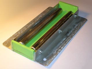
We will need: two shiny cylindrical doorhandles, a suitable piece of aluminium angle stock, an aluminium (or copper) rod or tube, some plastic and minor common tools.

Keep an eye for all conductive parts of the future discharger to be as straight as possible. I used some aluminium threshold in place of the anglestock. The neverending crysis with resources... Sorry about that. Let's hope that You wull be more lucky.

Cut the aluminium angle into size and round the corners.

Remove anodizing from the angle stocks (if exists) and grind the surface of doorhandles. Too shiny surface of electrodes would cause instabilities of breakdown voltage. It isn't good especially when You work near the threshold of dielectric failure. Drill holes for the screws and round the ends of the doorhandles.

Mount the doorhandles on the aluminium angle stock pieces.

Then You will need to assemble a box. It will be the housing of the discharger. A suitable way to do this is to hot glue plastic pieces to the angles and between each other. A hint there is to cover all places of attachment with a thin layer of hot glue and then to bake them with a gas torch.

Cut a piece of plastic of a suitable size. Its width should be calculated as:
w=2*height_of_doorhandle+diameter_of_central_rod+2*minimal_gap
Since my doorhandles have height of 16.3 mm (diameter of their cylindric part is 11 mm), diameter of my copper rod is 10 mm and since i want the discharger to have its total gap to be tuned from 3 mm to 6 mm (each of the gaps is then 1.5 mm), i take w = 16.3*2+2*1.5+10 = 45.6 mm.
It takes some efforts to make the piece of plastic to fit the needed sizes and at the same time to be even and rectangular, but it is worth of the efforts.
<
Place the sidewalls.

And place the opposite electrode of the discharger.

Mill a slot in each sidewall. (You really dont need a milling machine here. Since this is a plastic the milling can be performed by common drill.)

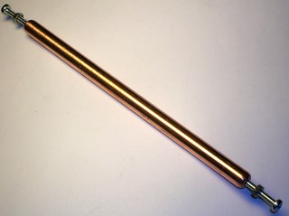
Here is a copper rod that will soon become the central electrode.

Drill and thread holes in its ends.

I used M3 thread here but it isnt necessary. Use the thread which suits Your needs best.


Dont forget to grind the rod and round its ends. A pair of screws (that will pass through the slots in the sidewalls) will keep the rod in the middle between side electrodes.

The free area of the slots in the sidewalls is a good source of loud sound when the discharger triggers. One should coverthe holes with something. E.g. with rubber stripes glued onto pieces of plastic .


The next part of the discharger is its top lid. It certainly can be opaque, but the tranparent one is more entertaining.


The lid should contain four slits. The width of each slit should be a bit above the half of the maximun (total) gap the discharger is intended for. The next photo shoes why. As my spark gap is intended for 3 mm to 6 mm spacings I will mill silits 3 mm wide.

It is shown here how to use some drilling bits to set up the spacing inside the spark gap. Each drilling bit here has 3 mm diameter. So the total spacing is set to 6 mm (2x3=6).

When You're done with spacing setup its time to secure the slits with something sound insulating. It appears that ribbon type sticky foam rubber works well.


The last stage is to fine tune the spark gap just in operation. The procedure resembles tuning of tea nitrogen laser. Hit the end screws easily with suitable tool until the spark gab begins to show not a single spark along its electrodes but many of them (see the left photo). Tighten the screws when done with tuning. The discharger is finally ready to use.
The right photo shows the discharger used in a small (air filled) nitrogen tea laser. The place available for me for photosession is limited (sorry about this) so You will have to take on belief that the laser with this discharger easily excites a cuvette with rhodamine 6g to lasing without any lense (cylindric or whatever) at the distancies up to 50 cm (20 inches). Coumarin lases more than one meter (40 inches) avay from the laser.
<< HOME PAGE |


