First time I knew about the inconvenient properties of the carborundum
from Jon Singer web reports, where he tried to use this substance to make
a preionizer for a nitrogen laser. However the success was rather poor,
and it is understandable that no will for attempts to reproduce this scheme
was arised. Moreover i already had a negative experience with attempts to
use a distributed resistance (in form of Bealieau schematics or capacitive
discharge). While the energy is low - the beautifull glow, and when You
try to reach laser level of energy deposition, the discharge contracts and
nothing helps.
Then a canadian article [1] appeared before my eyes. They praised silicon
carbide and a preionizer made of it. Their preionizer worked not worse than
a multi-spark one, but was much simplier and easy to build. However they
used a helium rich mixture (He:N2:CO2=70:15:15) and transition to air
substituted ones looked at least doubtfull.
At the third time silicon carbide hit my nose, when i tried to find in
literature some light on the process of huge energy dissipation in nitrogen
lasers. As usual: when You are looking for something, You find the very other.
The French article [2] reports that they succeeded to make working laser not
only using a heliumless mixture, but using a CO2:N2:O2=48:42:10, and that is
pretty close to using the air. (Actually the air containing mixture differes
from that one only by uncontrollable contaminations.)
Such a kick is hard to ignore so I had to give it a try. The silicon
carbide was found in form of grinding discs for hand engraver tool (dremel
tool). All that was needed, was to connect them to a little test circuit:
           SG
      +--->   <---+-----+---------+
      !           !     !         !
      !           !     !         !
      +----||-----+     \         !
      !    Cp           / Rl    XXXXX
      !                 \
     ---                /       XXXXX
     --- Cs             \         !
      !                 !         !
      !                 !         !
      +-----------------+---------+
SG - air filled spark gap. Cp - peaker capacitor Murata 590 pf x 40 kv,
Cs - storage capacitor Murata 2 nf x 40 kv. Rl - leakage resistor
(connects the opposite to the storage capacitor plate of the peaker to
the ground wire) 5.6 kiloohms,
The 'XXX' means silicon carbide electrodes.
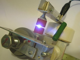
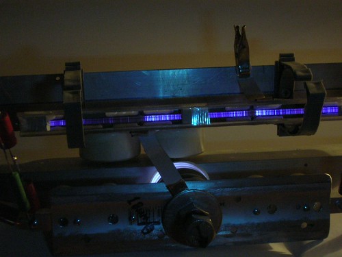
The result impressed me (see photo). Such an even and bright rain of sparks
I havent ever seen from any Bealieau circuit. And this sparky rain is
accompanied with a violet fog of a diffusion discharge.
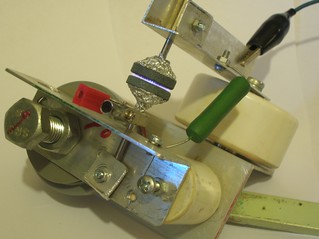
For the comparison here are the photoes of a discharge with analogous
grinding discs made of corund (Al2O3).
Despite the fact that the material is porous, it does not want to disperse
the spark. I.e. the reason of such a nice discharge with carborundum does
not hide in the fact that the discharge goes through thin pores between
abradant grains. The matter of fact is the conductivity of the carborundum
itself.
The test had clearly shown that at least as a preionizer this thing is
more than acceptable. And in better case it is good as a laser electrode.
However the hand engraver tool grinding discs arent best fit to make laser
electrodes. The search for the carborundum bricks in all nearby hardware
stores brought nothing. I had to make some web serfing. Finally those bricks
vere purchased:

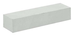
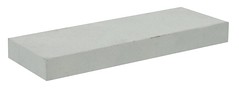
Despite that all of them (if trust the seller's price list) were made
of carborundum, in the test circuit they behaved differently. The bricks of
the first type (dark greenish grey, with large grains and pores size) give
dispersed rain of sparks as it was with Dremel's discs. The bricks
of the second and third types (greenish white, finely grit and nonporous
looking) behave like dielectric. It means the spark goes way around and
there's nothing between the bricks.
The bricks of the first type are 100x10x3.5 mm sized. The first test
laser was assembled with their use.
TEST 1
A laser tube was assembled. Its electrodes were formed by 100x10x3.5 mm
carborundum bricks. Three bricks per each electrode. The bricks have rather
foolish shape, so I slightly cut them to better fit the electrode keeper.
It appears that the carborundum bricks can be very easily cut with any diamond
tool. After the assemblage the active length of electrodes appeared to
be 285 mm.
The gap between electrode keepers was set by a props 10 mm thick. As the
result, the spacing between the laser electrodes became slightly less than
3 mm (were the bricks 3 mm thick, as it was said in the catalogue, it would
be 4 mm, but in reality the bricks appeared to be thicker).
No preionizer was introduced at this step. It was interesting whether the
silicon carbide could make all by itself.
The gas-discharge unit was put into a cut of plastic sewe pipe having
diameter of 50 mm and length of 300 mm. The ends of the pipe were shut by
perspex alignment mirror mounts. The back mirror was (as usual) the aluminium
coated concave automobile rear view mirror with its protective painting
having been removed. The front mirror was dielectric coated ZnSe with
75% reflection. The mirror was noticeably contaminated by a gas torch flame
in the vain attempts to make vacuum tight seal with a hot glue (glue-gun).
The distance between mirrors is 350 mm.
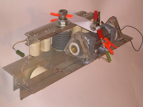
The laser tube was installed onto a frame with capacitors and spark gap
(that was left from a previous laser project). The resulting scheme is:
           SG
      +--->   <---+-----+---------+
      !           !     !         !
      !           !     !         !
      +----||-----+     )         !
      !    Cp           ) Ll    XXXXX
      !                 )
     ---                )       XXXXX
     --- Cs             )         !
      !                 !         !
      !                 !         !
      +-----------------+---------+
SG - air filled spark gap (the gap value is usually set to doubled
value of the spacing between the laser electrodes - matched load mode)
Cp - peaker capacitor 4 pcs Murata 590pf x 40 kV in parallel,
Cs - storage capacitor, from 3 to 7 pcs Murata 2 nf x 40 kV in parallel.
L1 - leakage inductor (shortens the circuit of the peaker capacitor
charging and limits the discharge time - 4 turns of 1 mm copper wire
in PVC insulation wound on a 45 mm corpse).
"XXX" - means carborundum
(laser electrodes)
   //You should better get used to the ascii graphics. Since it is a report,
   not a guide, I'm not going to slave Your habits - all the schematics will
   be in the form that I usually do: no "gif" or "jpg" for simple schemes.
   "txt" only. Try to adjust Your browser for not to eat whitespaces, or
   just open this in a text viewer/editor.//
The laser tube run at gap values (in the SG) from 6 to 11 mm, with
the storage capacity from 6 nf to 14 nf on mixtures of CO2:air 2:1, 1:1 and
1:2. At pressures from 500 mbar to 100 mbar. No lasing was observed.
Possible reasons:
- high diffraction losses (CO2 laser radiation with its long wavelength
poorly goes through the narrow spacing between laser electrodes)
- scattering on the discharge inhomogenities (The volumetic discharge is
accompanied by more than 10 000 sparkies. Each of them is weak, but the
total scattering may appear to be considerable. And the question of the
possibility of lasing using multitude of sparks only is still dark.
Bealieu himself had reported that his laser operated "on sparks" but
nobody later reported the same. So it was possibly misunderstanding or
bad translation or bas phrase.)
- the resistance of the electrodes gives high discharge time constant,
so the current prefers to go through L1. This is enstressed by the fact
that L1 was specifically choosen for fast lasers (sqrt(CsL1)~1mcs).
L1 was replaced by a high voltage wirewound resistor 5.6 kiloOhm rated.
The sparkies in the discharge became less weak more white. And at larger
storage capacities (above 10 nF) the strength of sparks was enough to burn
through th brick of carborundum. There appeared a burnout hole with black
border. Happily was only in single place, not all over the surface.
It was decided to add a preionizer. But before telling that results a pair
of words on the other interesting observations.
It is curious that the discharge in this laser tends to contract not
at high pressures, but on the contrary at low ones. Below 500 mbar I was
not able to obtain the volumetic discharge between the electrodes. Below
300 mbar I was not able to get ANY kind of discharge between the electrodes -
any discharge goes around them as if they were dielectric.
Another thing seeming unusual to me is a black color around the burnhole.
One may suppose that it is carbon, but... the brick easily endures gas torch
heating to about white glow. And when it is cold again it regains its color
and properties. So there is no organic glue in the brick's content.
One may suppose that SiC decomposes itself, but see above... I doubt
that the spark can heat it to comparable temperatures.
TEST 2
The laser tube was disassembled and a preionizer was added. The design
of the preionizer resembles Lamberton-Pearson scheme - two wires pulled
alongside the electrodes.
           SG
      +--->   <---+-----+---------+-----+-----+
      !           !     !         !     !     !
      !           !     !     Cpi---    !    ---Cpi
      +----||-----+     \        ---    !    ---
      !    Cp           / Rl      !   XXXXX   !
      !                 \         +---     ---+
     ---                /             XXXXX
     --- Cs             \               !
      !                 !               !
      !                 !               !
      +-----------------+---------------+
SG - air spark gap of the enclosed type, Cp - peaker capacitor 4 pcs of
Murata 590 pf x 40 kv in parallel,
Cs - storage capacitor from 3 to 7 pcs
of Murata 2 nf x 40 kv in parallel, Rl - 5.6 kOhm - leakage resistor
(shortens the charge contour of the peaker capacitor but unlike the
previous inductance almost does not affect the discharge time)
"XXX" as usual means carborundum, Cpi - preionizer capacitors, 50 pf each
KVI-2 type.
The preionizer wire has diameter of 0.5 mm. It is stretched along the
electrodes and placed in height coordinate exactly in the middle between
the electrode keepers (i.e. in 5 mm from the keeper plate surface).
The distance in the horizontal direction from the axis of wire to the
edge of the electrode is 2 mm. The wires are connected to the anode through
the capacitors goes not at both sides of laser (as one could suppose) but
at the end corresponding to the output mirror (I was low on capacitors that
moment).
Here I will again take an effort to remind You that this kind of preionizer
coincides the Lamberton-Pearson's one only by exterior and design. The
logic and principles of operation are completely different. Here the preionizer
uses thick wire and large capacity. And utilizes multi-spark discharge type,
that becomes possible due to the electrodes are resistive. Considering the
Lamberton's preionizer usually they say that utilizes corona discharge. And
I could simply say that it is completely different thing. However it would be
somewhat reduced thinking. The real corona is spatially limited discharge.
The ionization stops where the field is low enough. Unlike this in the
Lamberton-Pearson laser's working area there's no place where the field is
low enough for the ionization to stop. Actually the discharge does cover
all the path between the wire and the adjacent electrode. And since there are
no means to force the discharge to take distributed form, it tends to become
a "single bright arc" whenever it possible. In a very special cases when the
preionizer feeding capacitors have low value and the wire is thin the
discharge takes form of diffusion-streamer one. This one was studied in [3]
and they showed that the number of streamers increases with increasement of
voltage rising rate, with lowering of the wire diameter and with decreasement
of electron affinity of the gases. The single bright arc can not preionize
all the volume properly, so it's crucial for the discharge to have diffusion
streamer form. In practice it leads to very thin wires (below 100 mcm),
low feeding capacities, helium rich mixtures and low inductive power supply
circuits.
On the contrary here we have multi-spark discharge from thick wire to
the electrode with distributed resistance. The distribution of the sparks
depends mainly to the resistance of this electrode. Thick wire has lower
resistance and inductance. The preionizer feeding capacitors can have rather
large value. All this allows to increase power and energy of the preionization,
and moreover it allows to operate with voltage pulses having gradual front.
However despite all those advantages this preionizer is way less effective
than the one of barrier-discharge type used in laser with holed electrodes.
On the other hand it is way simplier. And when the preionizerless discharge
has the form very close to the needed one, it seems logical to begin with
the most simple solution.
And again the laser tube run at gap values (in the SG) from 6 to 11 mm,
with the storage capacity from 6 nf to 14 nf on mixtures of CO2:air 2:1, 1:1
and 1:2. At pressures from 500 mbar to 100 mbar. No lasing was observed.
The observable look of the discharge became more smooth but it seems not to
be enough.
TEST 3 (first light)
The laser tube was rearranged again. In order to increase spacing between
the laser electrodes one 1mm thick perspex plate was added to each spacing
prop. Hereby the spacing between the laser electrodes became 4 mm. The
placement of the preionizer wires was kept unchanged. I.e. they are still
at a height of 5 mm from the cathode keeper plate. The laser became asymmetric.
The preionizer wires are now placed (in vertical direction coordinate) at
5-3.5=1.5 mm from the cathode cutoff, and at 6-3.5=2.5 mm from the anode
cutoff.
The electrical circuit was kept unchanged. With Cs=6nf and with CO2:air=2:1 mixture at air pressure the lasing was observed. Almost accidentally.
It was noticed that just after the turning on of the laser the calorimeter
"behaves uneasy". Than it calms down and clearly shows zero.
Then the beam was focused onto a carbon paper. A spherical aluminium
coated mirror with focal length f=50 mm was used. Here it became visible
that the laser gives only the first 1-2 pulses in the sequence and then
dims. Due to my spark gap is of the uncontrolled type, I tried to reproduce
repetition rate change by repeatedly plugging the power supply to the mains.
It appeared that the laser was able to produce pulses at ~0.5-1 Hz (each
one or two seconds). And it was uncapable to do more.
It was supposed that preionizer feeding capacitives got charge from the
first pulse, and since the circuit is cut, they cannot discharge further on,
rather than through the huge and uncontrollable stray resistance. To take
things under control the leakage resistors were added:
           SG
      +--->   <---+-----+-------+-------+-----+-----+------+
      !           !     !       !       !     !     !      !
      !           !     !       /   Cpi---    !    ---Cpi  /
      +----||-----+     \       \      ---    !    ---     \ Rpi
      !    Cp           / Rl    /       !   XXXXX   !      /
      !                 \       \Rpi    +---     ---+      \
     ---                /       !       !   XXXXX   !      !
     --- Cs             \       +-------+     !     +------+
      !                 !                     !
      !                 !                     !
      +-----------------+---------------------+
Laser got run again. With Cs=6nf and CO2:air mixture 2:1 at full
athmospheric pressure (SG1 set to 8 mm) it gave more than in the first run.
Since power is low and unstable it is hard to say anything in figures but
subjectively the output raised by about 30%. With 1:1 mixture the output
raised once more and @ 1Hz laser yield ~6 mW. It still fails if attempting
to operate faster than once per second.
The preionizer connection was reworked. Leads were added at the back mirror
side of the laser. RpiCpi circuits are similar in all places (50pf x 5.6kOhm).
Since the number of such circuits is now 4 (each of two wires has two ends
and each end is feeded through RpiCpi from the anode) the total preionizing
capacity is now 200 pf.
Got a test run again. Still Cs=6nf and the mixture CO2:air=1:1 was used.
Pressure was 1 bar. At 1 Hz the laser gave ~12-15 mW. When turning onto a
self sustained repetition rate (about 30 Hz) it gives about ten pulses
until dims. The traces on the carbon paper became throughout holes (of course
with focusing).
There was an attempt to increase Cpi to 100 pf. Laser became unstable with
low and unpredictable probability of lasing. There appeared bright spark
discharges inside the laser tube. The sparks run not between the electrodes
but between electrode keeping plates, and one can see that the preionizing
wires play role of ignition electrode as in trigatron.
The Cpi capacitors were returned to 50 pf and the attempt was made to
increase storage capacity. One more 2nf Murata was added. The pulse energy
increased but the bearable repetition rate dropped. As the result the
average power decreased significantly (to ~eight milliwatts).
Interesting notice: when focusing to a carbon paper the plume (visible
spot where the beam hits the target) is not "electric-blue" as for powerfull
TEA lasers, but "yellowish-white" as for low pressure longitudinal CO2
lasers or for solid state free running ones. It probably means that the
resistance of the carborundum electrodes makes the pulse to became long,
possibly to several microseconds.
The main conclusion one can make is that most possibly the deal was
in diffraction losses. In TEA lasers with metal electrodes the last form
a waveguide that keeps wave losses at reasonable level and small spacing
between the electrodes becomes tolerable. The other situation is here:
the carborundum is coarse and highly absorbing. Why "most possibly" not "surely"? Because with higher spacings a higher energy deposition is
possible. There exists a possibility that increasement of energy deposition
with keeping the capacity at constant level (i.e. with smoother discharge)
might have played a role.
Still incomprehensible the nature of lasing stopping at higher repetition
rates. With metal electrodes my TEA's never had demonstrated such a problem,
at least up to 30 Hz.
TEST 4
Further increasement of the spacing between the electrodes. The gas-discharge unit was reassembled. The props between electrode keeping
plates were replaced by ones with 12 mm height. It gives interelectrode
spacing of 5 mm. The placement of preionizer wires relatively to the cathode
was kept intact. Correspondently the distance to the anode cutoff (by vertical
coordinate) has grown to 3.5 mm.
Tests of the unit at the open air with storage capacity equal to 4 nf has
shown nice uniform discharge. It seems miraculous to observe a uniform glow
of such a size in the air. Especially after such efforts directed to the
volumetic discharge ignition.

For the comparison here is a photo of the discharge with preionizer having
been disconnected. The difference is prominent, isnt it? By the way at smaller
spacings the difference is less significant.
The gap in the SG was set to 10 mm and with Cs=6nf the laser got a run on
CO2:air=2:1 mixture at athmospheric pressure. Yielded about 6 mW at ~1Hz.
Still shuts with repetition rate rising. In addition at the ends of the laser
cell there appeared white sparks (jumping from plate to plate via preionizer
wires).
Cs was increased more: to 10 nf (5 of Muratas). The power at low repetition
rate grew to 15 mW. And at last the laser became operational at free running
repetition rate (~10 Hz). It yields ~12 mW. I.e. relatively to the low rate
mode the pulse energy dropped more than 10 times. But it still lases.
However the white arcs at the ends of the cell become so strong that it
may cause troubles with the integrity of the laser.
One more experiment was made: the storage bank was connected to the laser
tube not by a wide metal foil strip as usual, but by a strip having 2 cm width
and 20 cm length (imitation of "feed-by-wire" mode). It still lased but
the power dropped by 4 times (from 12mW to 3 mW).
Conclusion: further increasement of the space between the laser electrodes
from 4 mm to 5 mm wasn't helpfull. With increasement of operation voltage the
preionizer began to work worse (to initiate sparks). So one needs to change the
place for the wires or to reduce the feeding capacity (which is undesirable)
or completely change the preionizer type. In addition there appear round path
breakdowns around the laser gap (not between the carborundum bricks but
between feeding wirings via the preionizer). And after it have sparked several
times there appear charcoal coating on the dielectric (on electrode keeping
plates or props). Such a coating fixes the birthplace of sparks and further
on laser becomes inoperational even at lowe voltages. I.e. when the voltage
is low enough its hard to ionize the gap between the laser electrodes and
(so the output is low) and when the voltage is high enough the gas discharge
unit fails and needs to be repaired. Seems that for the given size of the
carborundum bricks the voltage needed for normal operation (~30 kV) appears
to be too high.
TEST 5 (backstep) (25.10.2014)
Since the increasement of the spacing between the laser electrodes to 5 mm
has not brought any positive, the laser was reassembled back to the previous
configuration (with the inter-electrode spacing of 4 mm).
Then an attempt was made to increase the storage capacity with gradual
decreasement of voltage (only if needed, when too many sparks appear). Step by
step all seven Muratas were installed into the laser frame (14 nf total).
Strangely but there was no need to decrease voltage strongly. The optimal gap
in the main spark gap is near 7.5 mm.
Obviously the discharge is less stable than with 3 muratas for the same
conditions, but way more stable than with 3 muratas and 5 mm spacing between
the laser electrodes.
Lasing tests gave the next results (for not to type it everywhere i'll say
that the pressure was 1 bar/1000mbar/765torr in all tests here below. The
mixture was also without any additives such as xylene or any.)
- on CO2:air=1:1 mixture
The yield was 10 mW at 6 Hz. The power drop from the first pulses in
the sequence to the further ones is evident by the naked eye. The discharge
does also behave correspondently: the share of the violet glow reduces and
the share of the streamers grows. One may propose that it is due to the
electronegative ions accumulation.
- on CO2:combustor=1:1 mixture
Laser gave 42 mW at 6 Hz. Visually there's no drop of power from the
first pulses in the sequence to the subsequent ones. May be by a factor
of two or even less. (For ones who haven't read my other files, i should
remind that the "combustor" is the common air, where the oxygen was
burned out by combustion of a carbohydride fuel. In this particular case
it was done by burning ethanol - sometimes the type of fuel makes some
difference for the discharge form.)
- on CO2:N2=1:1 mixture
Laser gave 96 mW at 6 Hz. In comparison with "combustor" here's even
less drop of power from the first pulses in the sequence to the subsequent
ones. The plume of the laser spot has got a typical "electric" bluish
color. The nitrogen was of the technical grade from a high pressure bottle.
(Yes, I finally got one too. Could not resist to the temptation to find
out how much a nitrogen laser will yield when feeded by pure nitrogen.
However it is a different story.)
THE CONCLUSION: for particularly that carborundum bricks the spacing of 4 mm
between them is fairly optimal. The simplest build of laser, having wire type
preionizer appears to be operational with air:CO2 mixtures at full athmospheric
pressure. When feeded with comparatively pure gases it showed efficiency of 1%
by energy deposition. The reason of that rather low efficiency lies not in the
ohmic losses inside the electrodes. (Moreover now I don't believe that the low
efficiency in Bealieau laser was due to the losses in the resistors. Something
else there. Maybe too slow energy deposition in comparison with the upper laser
level effective lifetime.)
It is clearly seen that it wants higher preionization and maybe higher
energy deposition. For going further more carborundum needed. When I get some
the report will continue.
28.10.2014
The aluminium spherical mirror (the car rearview one, having been washed
out of protective paint) was replaced by a real laser one. The new mirror is
gold plated plano. The front mirror was kept intact. Other conditions are
unchanged too.
On CO2:combustor=1:1 mixture laser gave 9 mW at 6 Hz. Very careful alignment
while laser is running allows to grab as much as 18 mW.
The sense is that with a mirror, having greater reflection, but being plano,
it yields lower energy than with aluminium mirror having focusing properties.
It means that at such a spacing between laser electrodes the plano-plano
resonator already has significant diffraction losses. Significant enough to
lower the output power.
30.10.2014
A try to emulate the nitrogen by cleaning the combustor gas. One car tyre
was filled by the combustor. Then the gas was allowed to flow into another tyre
through a gas-mask filter. Then into that new tyre a technical grade carbon
dioxide from Crossman's cartridge was poured until the volume ratio became 1:1.
With this mixture the laser gave 36 mW (rep rate 6 Hz - the spark gap was
kept untouched).
After that a (fresh) mixture of Co2 with technical grade nitrogen (from a
cylinder) with a ratio of 1:1 was made.
Using this nitrogen mixture the laser gave 60 mW.
It means that cleaning of the combustor gas has gave nothing. The factor
of two difference between yields with nitrogen and with combustor hasnt gone
away. Seems it is due to undercombusted oxygen. It cannot be captured by the
active charcoal.
However the reason of yield decreasement in comparison with previous tests
does bother. The question why anything gets worse is always bothering.
Handlights having been bought a year ago light less brightly even with fresh
batteries. Year to year the cellular phone keeps connection at less and less
distance from the cell. And even when there it seems to be nothing to die...
As in case of this particular laser. Six carborundum bricks, two wires, two
mirrors and a few pieces of plastic. What can occure to that?
Its back mirror was removed, slightly and carefully polished with a paste
for cellular phones restauration. The front mirror was simply cleaned up.
Both mirrors were then placed back and aligned. The laser once again was
allowed to run on a CO2:N2=1:1 mixture. It gave 78 mW but rapidly degraded to
the previous 60 mW.
Front mirror was replaced by more reflective (and less badly used) one.
R=95%. Yield was 18 mW. The front mirror was again replaced. But this case
by less reflective (and more badly used) one. With R=50% yield was...
yield was... Well... At first it was very high. The light spot on the graphite
surface of the calorimeter was large and bright enough to make thoughts of
about 100 mJ or even more. But then the laser got died. It happened too fast to
get enough time to make measurements, so no figures, sorry for that.
Disassembling and defectation has shown some cleavages on two (of six)
carborundum bricks. Possibly the chips of SiC have shortened the preionizer
wires. Probably they could be shaken out without disassemblage of the laser.
31.10.2014
Laser was assembled back (without any modifications or repairings) and
started on nitrogenic mixture: CO2:N2=1:1. The output coupler was still 50%.
It lases. So the pieces of the carborundum definitely could be shakened out
and it was possible to continue the use of the laser without the ceremony of
disassemblage. The output, however, was only 30 mW. And no light on the
graphite at all. After those promising preliminary results it was a bit
disappointing.
To the tyre containing the nitrogen with carbon dioxide mixture a pair
of xylene drops were added. The drops were really small - may be of a 1.5
cubic millimeters. Then the tyre was shakened thoroughly to ensure even
distribution of the xylene vapours. The run on this mixture gave 78 mW.
The first 5..10 pulses show bright light on the graphite. Then it dims and
after ~3-5 seconds (18-30 pulses) there is no signs of light at all. Up to
that moment the calorimeter reading reachs about a half of their static value,
so I still cannot say anything definite about the energy of the first pulses.
So in previous experiments that were only my thoughts that the mixture was
free of xylene. In the reality the rubber tyre smelled with xylene remaining
from the previous tests. And with adding the fresh gas the amount of xylene
in the mixture decreased gradually. At first it came closer to the optimum
and the power of the laser raised. Further on it decreased away from the
optimum and the power began to drop and the laser started to spark. The last
fact actually had caused the cleavage of the electrodes.
The next test was an attempt to forsage the combustor:CO2 mixture by
adding some xylene too. There was no success though. The optimal concentration
of the xylene is rather low and in this case the xylene burns out fast in the
remains of oxygen. If we add too much xylene it burns out not so fast but it
begins to drop the output power by itself. As it was written in most articles: "the discharge became more uniform but no increasement of output power was
observed". That phrase just means that they didnt hit the optimum
concentration.
02.11.2014
Laser had worked for some time and died after that. It did about 1..2*10^3
of pulses with gradual dimming to complete darkness. Even for the mixture of
CO2 with technical grade nitrogen. Disassemblage and visual inspection have
found out nothing. It looks like everything is allright but it does not lase.
Moreover it doesnt even spark. At least it sparks not more than it did when
lasing was OK.
05.11.2014
A new small variant of laser was made. It has electrode length of exactly
one brick (10 cm). The preionization was made by Dumanchin-Farcy scheme:
    HV pulse _/\_  O------------+-------------------------------------+
                                !                                     ! Cpi
    |XXXXXXXXXXXXXXXXXXXXXXXXXXXXXXXXXXXXXXXXXXXXXXXXXXXXXXXXXXX|    --- 50
    |XXXXXXXXXXXXXXXXXXXXXXXXXXXXXXXXXXXXXXXXXXXXXXXXXXXXXXXXXXX|    ---
    |XXXXXXXXXXXXXXXXXXXXXXXXXXXXXXXXXXXXXXXXXXXXXXXXXXXXXXXXXXX|     !
     -----------------------------------------------------------      !
  ^                                                                  -+
  ! 4mm                                                     ________/ !
  V  ___     ___     ___     ___     ___     ___     ___   / ___      !
    |XXX| 0 |XXX| 0 |XXX| 0 |XXX| 0 |XXX| 0 |XXX| 0 |XXX| 0 |XXX|     !
    |XXXXXXXXXXXXXXXXXXXXXXXXXXXXXXXXXXXXXXXXXXXXXXXXXXXXXXXXXXX|     / Rpi
    |XXXXXXXXXXXXXXXXXXXXXXXXXXXXXXXXXXXXXXXXXXXXXXXXXXXXXXXXXXX|     \ 100k
                                !                                     /
                                !                                     \
                                !                                     /
                                !                                     !
                                +-------------------------------------+
                                !
                               ---
Dumanchin's preionizer is a plurality of insulated metal wires, placed in
grooves in the cathode. In the original form that were nickel wires inside
quartz tubings having diameter of 1 millimeter. Its clear that DIYer is out
of such a resources. If theres none nickel in quartz, how'bout copper in
teflon?
One of the carborundum bricks was grooved by means of some abrasive disc.
It was done by hand engraving tool, so the grooves aren't very even and
straight. However with some fortune one can put nearly 30 grooves over
the length of the brick. (The work appeared to be dirty and uneasy: dust and
spray flew directly into face. If You ever want to do such a thing be sure to
put on glasses and respirator.)
Copper wire in teflon insulation (russian MGTF trademark) was put into
the grooves and connected to the busbar of the opposite polarity. (Kinda
to the anode. Why "kinda" will be clear from the further reading.)
At first the spacing between the laser electrodes was set to 3 mm and
a test run was made. The discharge glow was very bright and uniform and
without any signs of streamers. As they say: "it can't be better!" Then
the spacing was increased to 4 mm with correspondent increasement of feeding
voltage. And here the bad things started. First of all the insulation of
the wire had failed, then the gaps and spacings in the schematic wiring
began to spark, then again the insulation of the wire... The geometry of
the laser auxiliary circuits was revised in order to increase the gaps, and
the attempt was made to reduce the electrical stress on the preionizer.
The direct connection to the opposite polarity was changed by the connection
through a rather small capacitor (50 pf) exactly as it is shown on the figure
above. However it didnt help the wire to survive. After that all available
insulated wires of suitable outer diameter (~1mm) were grabbed and tested.
Some failed earlier than MGTF, others appeared to be stronger. The one most,
strong to the electrical stress, that i have found looks like this:
can not surely determine its trademark by how it looks like. It is
elastic stranded wire, its insulation looks like PVC. And it was found
inside a very old LPT printer connection cable. Thats all i can say.
This wire withstood about three thousands of pulses when the
main spark gap was set to 12 mm (about 31 kV). Since in our laser the
voltage should be lower one may expect that this wire will show certain
lifetime. After the preionizer had been made of this wire the breakdowns
ceased. The volumetic discharge with some streamers was then obtained
for the interelectrode spacing of 4 mm. But for some reason the electrode
with the preionizer wishes to be anode. For the other polarity no glow
discharge appeared. Sparks only.
For the tests of lasing this little testbed was sealed into a cut of
two-inch PVC tubing with the mirror alignment units on the ends. The
mirrors were: the back one - aluminium on glass, spheric R=2 meters,
the output one - ZnSe, dielectric, ro=95%, plano. The distance between
mirrors was 185 mm. The gas mixture: technical grade nitrogen with
carbon dioxide from Crossman's cartridge, 1:1 proportion. Also an addition
of xylene was used in amount of ~5 cubic millimeters per 20 liters of
the gas mixture.
It lased without any difficulties. At the repetition rate of 1 Hz it yields
12..15 mJ per pulse. At higher rep rates it dims rapidly. As it was with the
previous type of laser: the first pulse is powerfull, the second one is weak,
and further on is darkness.
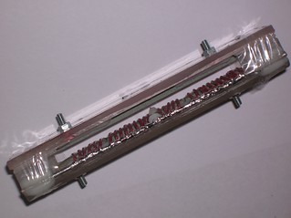
Here is how the laser looks like (dont look at the size of the frame, it is
just universal, and intended for placement of much greater devices. You better
go figure the size of the laser tube itself.)
 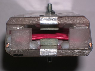
The storage capacity is 4 nf (it can be seen on the photo, that only 2
Muratas are used), charging voltage is 21 kV (8mm in the main spark gap), and
if the voltage of the glowing discharge is 3 kV/mm, then the charge, having
flown before dimming/contracting of the discharge, will be:
q=4e-9F*(21000V-4mm*3000V/mm)=3.6e-5 Cl
And the energy deposition in gas:
E=qU=3.6e-5 Cl*4mm*3000V/mm=0.43 J
I.e. the efficiency by the energy deposition is 2.8..3.4%.
And the full efficiency (related to the stored energy CU^2/2) is 1.3..1.7%
Even while remembering that we use rather clean gases, the efficiency
value obtained for such a short laser does impress.
In principle hereabove is a (not)great handwaving, because I've taken the
field tension for the stationary glow discharge to be equal to the breakdown
field tension for the air. (Even, not for the nitrogen!) But, say, in [4] they give 30..35 kV/cm for the field tension for the glowing phase in pure CO2.
10.11.2014
An ability of the short (10 cm) laser with Dumanchin's preionizer to operate
with mixtures with air and with combustor was proven. On the air:CO2=1:1 laser
gave ~6 mJ and for the combustor:CO2=1:1 it yielded less than 5 mJ - its hard
to measure due to low power and instabilities, but it gives definitely less
than with air. Its curious that the combustor, being usually better than air,
gives here such a fail. Most possibly it is due to contamination by water
vapours. The laser is short, the gain is small, and in above all that
the quenching by H2O appears.
With both mixtures the the top rep rate, when stable operation is possible,
is even less than with nitrogen: once per 2 sec for air based mixture and
something like once per 3 sec for the combustor based one. Pulse-to-pulse
stability became worse too. Consequent pulses may easily differ in energy
by the power of two. It looks like the laser sits just over the threshold.
In order to check a possibility to build the laser having no vacuum pump,
a test was done to run the laser with filling by washing mode. The laser was
evacuated (to less than 100 torr), then filled with air. Then the exhaust
pipe (at the rear mirror) was opened to the athmosphere and the inlet pipe
(the one at the front mirror side) was fed by the premixed N2:CO2 mixture.
When about 5 liters were flown down, it lased similarly to the case of air
with co2 mixture. After that 5 liters more of the mixture were allowed to
flow through the laser. After that it gave well formed laser spot when
observed by the light on a piece of carbon paper. Further on another 5 liters
of gas were passed through the tube. This time the lasing power was almost
undistinguishable from the one in case of tests with normal filling.
If the volume of the laser tube is VL=L*pi*d^2/4=13*3.14*5^2=255 ml, then
it results that the washing ratio should be k=V0/VL=40..60. If one can provide
such washing ratio when filling by gas blow, the laser will work well.
11.11.2014 GRIDDIE
A new laser was assembled. As it was in case of Dumanchin's one it has
electrode length the same as the length of the brick. Anode was made of one
carborundum brick 100x10x3 mm. Cathode - a grid from a kitchen sieve. The
power supply was made by this scheme:
       +---+------+-------------+---------------+------+
       !   !      !             !               ! Cpi  !
       !   !   5k6\             !               ! 50   / Rpi
       V   !      /             !              ---     \ 100k
          ---     \             !              ---     /
       ^  ---     /          XXXXXXX            !      !
       !   !4x570 !                          ---+------+
       !   !      !          ........_______/
       +---+      !          XXXXXXX
           !      !             !
           !      +-------------+
          ---  2 x Murata       !
          ---  doorknob         !
           !  2000pf x 40 kV    !
           +--------------------+
The kitchen sieve looks like this:

It was found out that the mesh can be easily removed just by unbeading
its frame. No need to cut anything. To flatten the mesh was also easy, despite
any infernal expectations. The size of the mesh cell is 2 mm. It better be
smaller, but one uses what he has. The spacing between the mesh plane and
the anode is 4 mm.
Behind the grid there is a preionizing electrode - a similar carborundum
brick. Size of the mesh is greater than the size of the brick with a reasonable
surplus. Pay attention to the fact that the brick, that is placed behind the
mesh, is not just a preionizer. Naturally all the supply current goes through
it. I.e. this circuit is the one with feeding through the preionizer. Ideally
it should provide preionization not only by the UV, but also by the electrons
having been extracted from the auxiliary discharge into the main discharge
by the electric field.
At the very first test the scheme sparked happily. The sparks went not
between the anode and the mesh, but between two carborundum bricks, through
the cells of the mesh. After a bit rework of the RC circuit of the preionizer
some glow was finally obtained. But... As it was seen from the end of the laser
the glow appeared not between the planar faces of the electrodes, but around
their sharp edges.
The edges of the bricks were rounded. This work can be done by a diamond
cutting disc and a hand engraving tool. What do You think, had the glow
moved to the planar faces? No. It disappeared completely. Only sparks remained.
In the torture process of the spark suppressing many things were done.
Even a guard discharger was added:
       +---+------+-------------+---------------+------+
       !   !      !             !               ! Cpi  !
       !   !   1k1\             !               ! 50   / Rpi
       V   !      /             !              ---     \ 100k
          ---     \             !              ---     /
       ^  ---     /          XXXXXXX            !      !
       !   !4x570 !                          ---+------+
       !   !      !          ........_______/
       +---+      !          XXXXXXX    V
           !      !             !       ^
           !      +-------------+-------+
          ---  2 x Murata       !
          ---  doorknob         !
           !  2000pf x 40 kV    !
           +--------------------+
The guard spark gap was known to help under the similar circumstances
(US.Pat 3940710). BTW it possibly helps by making a preionization of the
preionization spacing. (Yep, the box in the box.) But with this particular
laser it didnt help. The solution was found in making the electrodes thicker.
       +---+------+-------------+---------------+------+
       !   !      !             !               ! Cpi  !
       !   !   1k1\             !               ! 50   / Rpi
       V   !      /             !              ---     \ 100k
          ---     \             !              ---     /
       ^  ---     /          XXXXXXX            !      !
       !   !4x570 !          \XXXXX/         ---+------+
       !   !      !                          !
 +30kV !   !      !          ........_______/
    o--+---+      !          /XXXXX\    !
           !      !          XXXXXXX    V
           !      !             !       ^
           !      +-------------+-------+
          ---  2 x Murata       !
          ---  doorknob         !
 GND 30 kV !  2000pf x 40 kV    !
    o------+--------------------+
The slash characters near the crosses (meaning carborundum) are the silly
try to designate that the carborundum bricks have rounded edges. In addition
for the things to be more clear it was needed to show the power supply
connection points. Usually it is clear even to a fish, that the power supply
should be connected to the storage capacitor, but here the polarity of
the connection is important.
Now the electrodes (the main one and the undermesh one) are both glued
of two bricks being placed one onto another. The thickness of the carborundum
increased thus to 7 mm. The spark is still present, but at least it is
accompanied by the glow. The glow is visible by naked eye and finally
takes place between planar faces of the electrodes.
However the test of lasing have shown that the device is inoperational.
I.e. the intensity of the glowing discharge is too weak.
At the last despair try the scheme was "turned upside down":
  GND 30 kv
    o------+----------+-------------+---------+------+
           !          !             !         ! Cpi  !
           !       1k1\             !         ! 200  / Rpi
 2 x Murata!          /             !        ---     \ 100k
 doorknob ---         \             !        ---     /
  2000pf  ---         /          XXXXXXX      !      !
   40 kV   !          !          \XXXXX/      +------+
           !          !                       !
           !          !      ____.......      !
    o------+---+      !     /    /XXXXX\      !
 +30 kV    !   !      !     !    XXXXXXX      !
           !   !      !     !       !         !
           !   V      !     !       +---------+
    4x570 ---         !     !
          ---  ^      !     !
           !   !      !     !
           +---+------+---- +
The mesh became anode, the cathode became carborundum brick and the
undermesh electrode became banal preionizing electrode. The full supply
current does not flow through it after all.
The discharge test have shown a "sparky rain", and barely seen glow
at the background. As always in such cases it is not clear beforehand whether
it will lase or the sparks will interfere with lasing.
The laser was started on N2:CO2=1:1 mixture. The resonator was the same as
for previous one (back - Al on glass, sphere, measured R>96%; front - plano,
ZnSe, R=95%). At rep rate of 1 Hz it gave 8..10 mJ. What is more curious it
does not dim with rep rate rising. At ~10Hz it gives ~18 mW, that means 1.8 mJ
per pulse.
However with the combustor based mixture it behaves differently. Not only
it ceases with rep rate rising, it shuts also with time passed - even at the
rep rate less than 1 Hz it gives 5..10 pulses until fading. After that
even the filling by the pure N2:CO2 mixture does not bring it to consciousness.
Only after a long pause (more than 1 hour), and after having been filled by
a fresh pure mixture it begins to lase. I.e. it appears to have a property
to be capable to be poisoned by bad gases.
CONCLUSIONS:
- with good gases the grid-based laser is better than the Dumanchin's one.
it gives the same power but lives at higher repetition rates. With bad
gases the Dumanchin's laser is better.
- for the normal laser operation it needs the sum thickness of the
carborundum electrodes to be twice greater than the spacing between the
electrodes. That's particularly why there was the fail in increasement of
the spacing to 5 mm and above.
- once again it was proved that nothing certain could be said by visual
observations of the discharge. In some cases it lases with sparks in
the laser channel, in other cases it refuses to lase even with a fine
glow.
12.11.2014
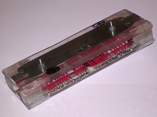
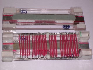
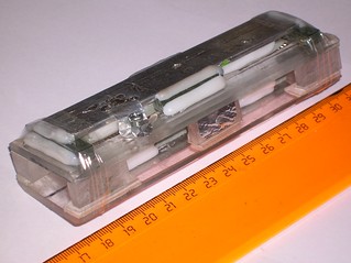
Here are the photoes of the laser internals. One can see the mesh, the
carborundum brick behind the mesh, and the fact that the bricks are put
one onto another in order to increase the total thickness of the carborundum.


The griddie laser was run on a mixture with air. It lased but weakly.
The power was unmeasurable by my calorimeter. The light spot on carbon paper,
produced by its focused beam was little - literally having the size of one
pixel. And the pixel is weak, and it does not appear any time.
The tests were made with mixtures of CO2 with air in proportions from 2:1
to 1:2.
| CO2 |
: |
AIR |
|
QUALITIVE CHARACTERISTIC |
2 |
: |
1 |
- |
weak pixel |
1 |
: |
1 |
- |
bright, but still pixel, not strip or macroscopic spot |
2 |
: |
3 |
- |
weak pixel again |
1 |
: |
2 |
- |
no lasing at all |
In any of the tests the lasing was unstable. And it does not seem that
the laser wants low repetition rate, i.e. certain delay between pulses.
It just hard to say whether in this particular pulse will be any lasing
or not. At the rep rate of 1 Hz the laser spot appears with a probability
~10%. And at rep rate of 0.1 Hz it does still appear with a probability
of ~10%. Moreover the first pulses in the sequences tend to be without lasing.
However in the contrast to the combustor based mixture, the air based ones
do not poison laser. I.e. after a certain pause and with fresh batch of gas
it was possible to see lasing again and again.
Generally i believe
(i cannot prove it seriously, so it remains only to believe) that in lasers with the unlimited speed of energy deposition (ones based on metal electrodes, low inductance capacitors, having low inductance wiring, fast spark gap and correctly choosen peaker) the highest gain takes place on the mixture proportions of 1:1 It seems that the energy here is at top too. In lasers with slow energy deposition (Bealieau type and etc.) it can happen that the optimum will go to the higher nitrogen proportions, since the vibrational levels live in it sufficiently longer
Concerning the mixtures with technical grade nitrogen, it need be said,
that this design of laser appeared to be very sensitive to the gas quality.
With the mixture having been stored in (rubber) tyre overnight the output
drops three times in comparison with the fresh mixture.
In order to increase the preionization effectiveness a try was made to
introduce a delay between the preionizing and the main pulse. Due to laziness
the most simple way to do this was selected. (See US Pat. Appl. 10/612848).
The anode was simply connected with the cathode by a dumb shunt capacitor,
and into the feeding circuit a delay element is inserted. The authors of
the mentioned application used an inductor, and here i placed a spark gap)
  GND 30 kv
    o------+----------+---------------+---------+------+
           !          !               !         ! Cpi  !
           !       1k1\   +---+       V SGD     ! 200  / Rpi
 2 x Murata!          /   !   !       ^        ---     \ 100k
 doorknob ---         \   !   +-------+        ---     /
  2000pf  ---         /  ---       XXXXXXX      !      !
   40 kV   !          !  --- CD    \XXXXX/      +------+
           !          !   !  470pf              !
           !          !   !    ____.......      !
    o------+---+      !   !   /    /XXXXX\      !
 +30 kV    !   !      !   !   !    XXXXXXX      !
           !   !      !   +---+       !         !
           !   V      !       !       +---------+
    4x570 ---         !       !
          ---  ^      !       !
           !   !      !       !
           +---+------+-------+
It run with N2:CO2=1:1 with the previous resonator.
It lases but worse than without CD and SGD. Maybe too much is lost on the
spark gap.
A try to replace it with an inductor (LD on the scheme):
  GND 30 kv
    o------+----------+-------+-------+---------+------+
           !          !       V       !         !      !
           !          !       ^  SGD  )         !      !
           !          !       !       )         ! Cpi  !
           !       1k1\   +---+       ) LD      ! 200  / Rpi
 2 x Murata!          /   !   !       !        ---     \ 100k
 doorknob ---         \   !   +-------+        ---     /
  2000pf  ---         /  ---       XXXXXXX      !      !
   40 kV   !          !  --- CD    \XXXXX/      +------+
           !          !   !  470pf              !
           !          !   !    ____.......      !
    o------+---+      !   !   /    /XXXXX\      !
 +30 kV    !   !      !   !   !    XXXXXXX      !
           !   !      !   +---+       !         !
           !   V      !       !       +---------+
    4x570 ---         !       !
          ---  ^      !       !
           !   !      !       !
           +---+------+-------+
When LD is formed by a copper wire, 1 mm in diameter and 5 cm long, and
when this wire is bend nearly to half of a ring the things seem to be quite
close to the optimum and the laser yields the same energy as it did without
all this stuff (SGD, CD and LD). It gives less with larger and lower values
of the LD. It is Curious that when LD is formed by 3-turns coil, wound on
a tubing having 50 mm diameter, the SGD begins to spark. Need to note that
SGD naturally had form of a spacing between the laser tube lead and the
laser frame base, so it could not easily be removed from the scheme completely.
With such a coil (3 turns 50 mm diameter) laser gives energy intermediate
between the optimal one and one in case of only SGD usage.
Again I should note that I'm not scientist - I'm a DIYer. With my instruments and resources the difference by a factor of two is "insufficient" one, it should better be treated as subjective rather than objective difference. Only the difference by an order of magnitude does really mean something.
Hence if in addition one succeed in proving that the preionizer of this
scheme is also tolerant to inductance, it will appear to be that this scheme
can really be "fed by wire". However I have no zeal to do it, since the
griddie laser has shown other shortcomings - first of all the evil sensitivity
to the gas quality.
17.11.2014 STANDIE
With the griddie laser it was found out that the carborundum should have
a certain thickness for the good operation (best if the thickness is nearly
equal to the twice of the value of the spacing between the electrodes). Since
that it seemed that a good way for increasement of the inter electrode
spacing is to increase the thickness of the carborundum, and the very way
to do it is to set the bricks in "standing pose." So the bricks were made
to stand on their narrow face:
  //////////////////  <-perspex platform
     XXXXXXXXXXX
     XXXXXXXXXXX <------Carborundum brick
 ^
 ! 4 mm
 V
    O XXX O XXX O
      XXX   XXX  \  wire d=0.5mm
      XXX   XXX   \-------------
      XXX   XXX
      XXX   XXX <------Carborundum brick
      XXX   XXX
  //////////////////  <-perspex platform
         <->
          2 mm
Two down bricks were installed in standing pose and the upper brick was
put as lying on its holder plate. Between the standing bricks, along them,
some wires were stretched. If the wires are insulated the schematic becomes "longitudinal Dumanchin's scheme". If they are naked it becomes something
intermediate between Dumanchin's and Lamberton's ones.
If there is no insulation, there is nothing to breakdown. So at first
the naked wires were choosen. The wires were connected to the other polarity
by individual capacitors Cpi1...Cpi3
   +-               -+------+----O _/\_ HV pulse
   ! \_____________/ !      !
   !   XXXXXXXXXXX   !      !
   !   XXXXXXXXXXX   !      !
  ---               ---    ---
  --- Cpi1      Cpi2---    --- Cpi3
   !                 !      !
   +--O XXX O XXX O--+      !
        XXX ! XXX           !
        XXX ! XXX           !
        XXX ! XXX           !
        XXX ! XXX           !
        XXX ! XXX           !
   +-------------           !
   !        !               !
  ---       +---------------+
   -
(Ground)
Or by common capacitor Cpi:
   +-               -+------+----O _/\_ HV pulse
   ! \_____________/ !      !
   !   XXXXXXXXXXX   !      !
   !   XXXXXXXXXXX   !      !
  ---               ---    ---
  --- Cpi1      Cpi2---    --- Cpi3
   !                 !      !
   +--O XXX O XXX O--+      !
        XXX ! XXX           !
        XXX ! XXX           !
        XXX ! XXX           !
        XXX ! XXX           !
        XXX ! XXX           !
   +-------------           !
   !        !               !
  ---       +---------------+
   -
(Ground)
The leakage resistors (in parallel to the capacitors) arent shown on the scheme
for the sake of clarity. However in reality they were installed.
The assembly was tested in open air. The storage capacitor was 2x2 nF, the
main spark gap was set to 8 mm. Paradox, but the second schematics (all wires
are soldered together and connected by the common capacitor) shows visually
better discharge than the first schematics, where the preionizing wires are fed
by individual capacitors. Even if the condition of Cpi1+Cpi2+Cpi3=Cpi
is observed.
The assembly was then installed into the plastic tube with resonator (the same
as the above and the above of the above) and tested with the N2:CO2=1:1 mixture.
NO LASING. Even with fresh gas. Even at low rep rate. Even at the spacings
up to 12 mm in the main spark gap (up to 31 kV). Neither with individual
capacitors nor with common one.
OK then. The next is the longitudinal Dumanchin's scheme. The naked wires
were replaced by the insulated ones (see note of 05.11.2014)
          -               --------+----O _/\_ HV pulse
           \_____________/        !
             XXXXXXXXXXX          !
             XXXXXXXXXXX          !
                                  !
                                  !
                                  !
  +--------(O)XXX(O)XXX(O)--------+
  !           XXX ! XXX           !
  !           XXX ! XXX           !
  !           XXX ! XXX           !
  !           XXX ! XXX           !
  !           XXX ! XXX           !
  !      +-------------           !
  !      !        !               !
  !     ---       +---------------+
  !      -                        !
  !   (Ground)                    !
  +-------------------------------+
(o) - means here the insulated wire.
The discharge became more even. The sparks became more weak. But still no
lasing at all.
A proposition: the resistance of vertically standing bricks is too high.
Or, to be more correct, the field is too weak to cause the avalanche
breakdown in the carborundum. (Since the SiC is semiconductor, it seems to be
capable to enter the state of high conductivity, when the applied electric
field reaches a certain threshold.)
For the checkout only two bricks were left:
          -               --------+----O _/\_ HV pulse
           \_____________/        !
             XXXXXXXXXXX          !
             XXXXXXXXXXX          !
                                  !
                                  !
                                  !
  +----------(O) (O) (O)----------+
  !          XXXXX!XXXXX          !
  !          XXXXX!XXXXX          !
  !         /-----!-----          !
  !      +--      !               !
  !      !        !               !
  !      !        !               !
  !     ---       +---------------+
  !      -                        !
  !   (Ground)                    !
  +-------------------------------+
And along one of them three insulated wires were put. The spacing between
wire and the other side brick was set to 4 mm. The assembly in the essence is
longitudinal variant of Dumanchin's scheme without any grooves. It is much
simplier to be made than the one described above.
Lasing test has shown the prominent absence of lasing.
Then the spacing between bricks was reduced. It became 4 mm between the
bricks themselves (not between wire and brick as above). The central wire was
removed for not to make obstacles on the long wave light pass.
          -               --------+----O _/\_ HV pulse
           \_____________/        !
             XXXXXXXXXXX          !
             XXXXXXXXXXX          !
                                  !
                                  !
                                  !
  +----------(O)     (O)----------+
  !          XXXXXXXXXXX          !
  !          XXXXXXXXXXX          !
  !         /-----------          !
  !      +--                      !
  !      !                        !
  !      !                        !
  !     ---                       !
  !      -                        !
  !   (Ground)                    !
  +-------------------------------+
Such a scheme hadn't refused to lase. With the negative polarity on the
electrode with the preionizer the laser yielded 3.6 mW @ 1 Hz and 24 mW
@ 16 Hz (1.5 mJ for those lazy to use calc.exe). With the positive polarity
on the electrode with the preionizer, it gave 4.2 mW @ 1 Hz and 30 mW @ 16 Hz
(~2 mJ).
Maybe it is not much, but in comparison with all previous carborundum lasers
it shows amazingly low dropdown with the increasement of the rep rate.
By the way, I hope that You are already got used to the ASCII graphics. Up
to this moment the file already contains 17 schemes. In the pixel form I'd
got mad to draw them, and You - to download them.
20.11.2014 SPARKY
↑
OK, we've reached the point to test a "classic" scheme with spark type
preionizer. Possibly most of You were quite impatient to wait for these
results.
The most simple scheme is going to be assembled:
  +---+------+----+----+----+----+------+
  !   !      !    !    !    !    !      !
  V  ---    ---  ---   !   ---  --- Cpi !
     ---    ---  ---   !   ---  ---     !
  ^   !Cp    !    !  XXXXX  !    !      !
  !SG !      V    V         V    V      /
  +---+      ^    ^         ^    ^ SGpi \ Rb
      !      !    !  XXXXX  !    !      /
      !      !    !    !    !    !      \
     ---     +----+----+----+----+      /
     --- Cs            !                !
      !                !                !
      +----------------+----------------+
For the sake of the simplicity it is not shown that in parallel to
each preionizing capacitor a 5.6 kOhm resistor is connected. There are
also shown only 4 of the capacitors. In reality there are 8 of them.
As a few previous variants this laser has short electrodes. Their length
is equal to the length of one carborundum brick. The inter-electrode spacing
will be set to 4 mm.
Additionally in the process of the assemblage it was found out that my
caliper was broken. So the sizes in the previous variants of lasers (and
especially the interelectrode spacing) may have been measured incorrectly.
I hope the error was small, but if You want to reproduce one of the lasers,
You should be prepared to +-1 mm variations. Just to stay on the safe side.
The preionizing spark gaps are made of M3 screws and placed in 1 cm from
the electrode(s) and in 2 cm from each other. Totally 8 spark gaps (see the
figure):
                   20 mm
               !<-------->!

          -    O          O          O          O
          ^
     10mm !
          V
          XXXXXXXXXXXXXXXXXXXXXXXXXXXXXXXXXXXXXXXXXXXXXXXXXX
          XXXXXXXXXXXXXXXXXXXXXXXXXXXXXXXXXXXXXXXXXXXXXXXXXX
          XXXXXXXXXXXXXXXXXXXXXXXXXXXXXXXXXXXXXXXXXXXXXXXXXX
          ^
     10mm !
          V
          -         O          O          O          O
                               !<-------->!
                                   20 mm
The gap in the spark gaps is to be set to 2 mm. It should be mentioned that
for correct operation the preionizing spark gaps MUST fire BEFORE the
main laser channel ignites. Therefore the gap in the preionizing spark gaps
should be choosen (much) shorter than the main interelectrode spacing.
The typical mistake of amateur laser-builders is the hope in some "non-self sustained discharge controlled by the external UV radiation". Drop it. When a necessary voltage is already applied to the electrodes the affect of any external radiation will cause nothing but spark. The preionization is called so exactly due to the fact that it must be applied before. Up to the moment of sufficient voltage application to the main laser electrodes the gas between them MUST ALREADY BE CONDUCTIVE. Only in that case You have a chance to obtain glowing phase of the discharge.
24.11.2014
The laser was finalized and tested at the next conditions: Cs=6nf, Cp=4x510pf,
Cpi=100pf, Rb=1 kOhm, and in parallel to each Cpi a leakage resistor rated to
5.6 kOhm was installed. The spacing in the main spark gap was 8 mm.
Without artificial limiting of the repetition rate (it did ~16 Hz) the laser
gave:
| With mixture of |
technical grade nitrogen:CO2=1:1 |
78 mW |
(4.8 mJ) |
| With mixture of |
air:CO2=1:1 |
96 mW |
(6 mJ) |
| With mixture of |
combustor:CO2=1:1 |
84 mW |
(5.2 mJ) |
Dont think that the things are bad with the technical grade nitrogen. Just
the mixture was too old (was mixed abt ~3 days ago). The last two mixtures were
fresh. It is more correct to consider that with all mixtures the laser gave
the same energy in the limits of measurement errors.
With any mixture the laser spot on carbon paper is yellowish white without any signs of blue "electric" color.
An attempt was made to add an inductor into the feeding circuit:
  +---+----+     +-----+----+----+----+----+------+
  !   !    !     !     !    !    !    !    !      !
  V  ---   )     !    ---  ---   !   ---  --- Cpi !
     ---   ) Lt  !    ---  ---   !   ---  ---     !
  ^   !Cp  )     !     !    !  XXXXX  !    !      !
  !SG !    !     !     V    V         V    V      /
  +---+    +-----+     ^    ^         ^    ^ SGpi \ Rb
      !                !    !  XXXXX  !    !      /
      !                !    !    !    !    !      \
     ---               +----+----+----+----+      /
     --- Cs                      !                !
      !                          !                !
      +--------------------------+----------------+
Lt - was a ~30 cm long cut of flexible copper wire in vynil insulation.
The section of the wire was about 1 square mm. The laser was then tested with
the air:CO2 mixture. It lased. However the output power was 4 times lower than
in the previous tests. After the usual type of connection had been restored the
power did not return to the previous level.
Disassemblage and defectation have shown that one of the carborundum bricks
was broken (possibly by a spark). I.e. one cannot say that the stray inductance
has directly diminished the output. It just made the sparks to appear more
easily. And the sparks in their turn damaged the electrode.
After the scheme will be repaired I should check the operationability in
the "fed-by-wire" mode again, and also I need measure the output at the low
repetition rate.


PRELIMINARY CONCLUSION:
- THE CLASSIC IS THE CLASSIC. It shows good results. But it is due to
some reasons.
- Very high energy of the preionization (more than 14% of the total in
the storage capacitor) helps. Despite the large distance between the
laser channel and the spark gaps it still works.
- the leakage resistors in parallel to the preionizing capacitors were
intentionally choosen as low as 5.6 k. The idea is to provide the UV
lighting of the laser channel even after the capacitors Cpi have
already charged. Even after that with such a low resistance there
exists a continious arc discharge. It is known that all negative ions
have very low ionization potential and can be decomposed even by the
long wave UV radiation. The continious lighting should provide
negative ions decomposition and releasement of the free electrons at any
stage of the discharge. Judging from the operation of the scheme with
the air based and combustor based mixtures the principle really works.
I.e. the continious UV lighting does compensate the bad action of the
electronegative gases, such as oxygen.
25.11.2014
The broken brick in the laser was replaced with another one. The laser got
a test run. The yield was miniscule. The cause was the replacement brick. It
has a trace of a spark breakdown from previous experiments. Maybe due to this
fact or maybe due to its own properties (such as e.g. low conductivity) but
when this brick is installed the glow is weak and the spark is strong.
Another replacement of bricks was performed.
This time the laser seemed to resurrect: 84 mW at 16 Hz rep rate.
At 1 Hz it gave 9 mJ. I.e. the energy drop with the rep rate increasement
was rather low - less than twice.
In order to test the ability to operate with a "high inductance" power
supply the laser was connected as follows:
      +------->  <-----+----+----+----+----+------+
      !        SG      !    !    !    !    !      !
      !               ---  ---   !   ---  --- Cpi !
     ---              ---  ---   !   ---  ---     !
     --- Cs3           !    !  XXXXX  !    !      !
      !                V    V         V    V      /
     ---               ^    ^         ^    ^ SGpi \ Rb
     --- Cs2           !    !  XXXXX  !    !      /
      !                !    !    !    !    !      \
     ---               +----+----+----+----+      /
     --- Cs1                     !                !
      !                          !                !
      +--------------------------+----------------+
The storage bank was formed by three mylar film rolled capacitors of
K73-14 type (0.015mcF x 10 kV) having been connected in series. In parallel
to the main spark gap SG there REALLY was NO PEAKING CAPACITOR. It was not
an error, it was a survival test. Rb=100kOhm. All connections were made by
a flexible wire having ~1square mm section. The spacing in the spark gap
was set to 8 mm.

It's amazing, but the laser was able to operate. It gave 40 mW at 11 Hz
repetition rate. It worked for a few minutes (just enough to measure its
power) and died.
It was found out that in the bricks there appeared a new hole made by a
spark. And instead of the nice glow there are only sparks when trying to
turn on the laser.
THE CONCLUSION:
Generally speaking we've got almost perfect scheme of laser.
- It works at athmospheric pressure with gas mixtures of almost any
purity grade, regardless whether they contain oxygen or not.
- It keeps the energy output with increasing the repetition rate.
- It provides high gain - even the laser with its electrodes as short
as 10 cm was capable to operate with decent efficiency and output.
- It gives long pulse - the dream of many CO2-laser designers. I probably
won't make much error if I say that it has duration of several
microseconds.
The scheme has only single one shortcoming:
- IT IS NOT RELIABLE!
While there is an even glow discharge - all things are OK, but when
a spark appears it means the carborundum is dead. And there's almost
no way to completely avoid the appearance of sparks.
The operation of the scheme was so impressive that a proposition appeared:
what if this scheme is better than the one with holed electrode and the barrier
discharge preionizer. May be all these years we've played fools and the first
fails with the classical scheme were nothing more than experimental mistake.
For the test purposes two aluminium electrodes were made. They have shape of
parallelepiped with all edges having been rounded. 10 mm wide, 100 mm long
and 4 mm in height. The working side of the electrodes was polished.
Those electrodes were installed in place of the carborundum ones and the
laser tube was connected to the low inductance pulse supply (the one with
Murata capacitors). Cs=4nf.

The tests with gas mixtures based on air and on combustor have shown no
miracle. With the metal electrodes the scheme produces sparks only. No glow,
no lasing. No light inside the tunnel. It does not produce the glow even
when having been pumped out to 25 torr. A bit disappointing. But on the
other hand it means that the laser with drilled electrodes and with
barrier discharge preionization was discovered not in vain. In its most
primitive modifications it gives volumetic discharge with air based gas
mixtures at 200..300 torr, and the last variants of this laser are
operational with air:CO2=1:1 at slightly higher pressures than a full
athmosphere.
03.12.2014 LYRICAL RECESSION - CAPACITIVE LASER
↑
When speaking regardless to the laser parameters it is quite easy to
obtain a volumetic discharge in the air at athmospheric pressure. Take two
metal pieces without any sharp edges, wrap them into dielectric foil.
(The dielectric should be thin and electrically strong. Mylar is a good
choice.) Connect these electrodes to a source of high voltage alternating
or pulsed current. Enjoy the result. In some papers they call this kind of
the discharge as "corona on (at) the dielectric surface". As for me, I like
the term "barrier discharge". In sounds more reasonably.
However any attempts to fill the volume of the discharge with laser gas
mixture and to put all this into the resonator will only lead to fail.
The energy deposition is too low here.
To ensure this we can make some simple estimations. Let Egas - is the
field tension corresponding to the discharge glow in the gas (let me remind
that it is equal to the breakdown voltage in the uniform field if we pretend
the accuracy range not better than 10..20%. For the air it will be 30 kV/cm.)
Let Ed - is the electric strength of the dielectric and e - its dielectric
permeability. Apparently the top value of the electric charge q, that can be
passed through a unit of dielectric surface (without breaking it) is equal
to the specific (to the unit of area) capacity multiplied by the charging
voltage (for the obvious reasons the latter cannot exceed Ed*delta):
q = Ed*delta * e0*e/delta = 8.85e-12*e*Ed
Curiously that the thickness of the dielectric delta has gone. And the
laser feeding voltage hasnt been left in the expression too. The limiting
charge per unit of area appears to be related only to the properties of the
dielectric.
From the experience of nitrogen lasers we know, that the mylar foil can
hold as much as 10 kv per each 100 mcm of thickness. I.e. 100 kv/mm or 1e8 V/m.
The reference value of the dielectric permeability of the
polyethyleneterephtalate (this is the true name of the mylar) is e=4. However
my own measurements of the capacity approve only e=2. So:
q = 8.85e-12*2*1e8 = 0.0018 Cl/sq.m = 0.18 mcCl/sq.cm.
The electric power is definitely the electric current having been multiplied
by the voltage drop (on the part of the circuit). The voltage drop on the gas
discharge is a very conservative value. So conservative that some time ago some
gas discharge stabilitrons were produced. I.e. the circuit with the gas
discharge can be approximated with a circuit having a stabilitron with a
reference voltage of Egas*Delta:
                  o                  o
                  !                  !
                  !                 ---
               -------              ---
               =======               !  Ust=Egas*Delta
                                     +---L<|---+
               =======                         !
               -------               +---------+
                  !                  !
                  !                 ---
                  o                 ---
                                     !
                                     o
The electric energy deposited in the gas (on the stabilitron) is:
W=S*q*Ust=S*q*Egas*Delta
Where S - is the area of the electrodes (area of the discharge cross
section) and Delta is the value of spacing between the laser electrodes.
The energy specific to the unit of volume is:
w=W/(S*Delta)=q*Egas ; w=8.85e-12*e*Ed*Egas
As we can see all the technical parameters (area and height of the
discharge) have gone again and we left with the electric parameters of the
dielectric and the gas only.
For q = 0.18 mcCl/sq.cm, and Egas=30 kV/cm (the discharge in the air
between mylar insulated electrodes): w=5.4 mJ/cub.cm=5.4 J/liter.
Most TEA lasers have the threshold of lasing at 50..70 J/liter. And from
the formulas above it can be clearly seen that neither voltage variations
nor dielectric thickness changes can help to improve the situation. Only
other dielectric type can help. Such as barium titanate, that is used in
the ceramic capacitors. But it is the very other story.
Thinking on the obtained formulas gives another curious conclusion.
One should remember that the Ed decreases with the dielectric thickness
increasement. If we have something about 100 kV/mm for the thin mylar foil,
it will drop to somewhere near 30..50 kV/mm when we use the mylar with the
thickness of about 1 cm. It means that the capacitive laser should be kinda
low voltage with thin dielectric rather than high voltage with the thick one.
The said above is true for the case of single charge. And if we can recharge
the capacities N times during the necessary time, the energy deposition will
grow N times. The value of N is understandable: if we want the energy
deposition to be at the level of "good" lasers then N =200J/l / 5J/l =40.
And how long can be is that "necessary time"? The energy must be put in
the gas before the carbon dioxide will loose it. In other words the energy
deposition time must be less than the lifetime of CO2 molecule at the upper
laser level. The lifetime of CO2 having been mixed with air and at athmospheric
pressure is kinda hard to find in literature. The very rough estimations
give something like 1 mcs. I.e. one should be able to recharge the laser
electrodes 40 times during 1 mcs of time. Thus the feeding frequency will be
10 MHz (4 recharges per full period of oscillations). If we orient to the
feeding energy of 1 J it will mean the power of the HV generator of
1 J/1mcs=1 MW. Its a dead end. The results of attempts to create 1 MW
rated HV HF power supply can be seen here
Apparently its unreal to make the capacitive discharge laser based on
the mylar dielectric. However the previous test laser (the sparky) has
shown that things can be not so bad. It was operational when fed by
the capacitors that just cannot discharge faster than in 4 mcs. So the
estimation of the necessary energy deposition time can be corrected to
the better direction.
One way or another, but the capacitive laser was created.

Here is the
scheme of its design.


Its body is the old good plastic sewer pipe, 2 inch in diameter. The laser
electrodes are made of the pieces of another plastic tubing. This one has 20 mm
outer diameter. The conductive part of the electrodes (the plates) is formed
by sticky aluminium tape. And the barrier layer is formed by 120-mcm mylar
foil. The working length of the electrodes is 100 mm. The full length of the
laser (mirror-to-mirror) is 205 mm. The mirrors are just the same as were in
the previous and the pre-previous lasers.
Here is the connection schematics:
                  +--/\/\/---+
                  ! Cpi      ! +-/\/\/\--+
   +---||---+     +----||----+ !         !
   !        !     !          ! !         !
   !        !     !        +---+-||-+----+
   !        !     !        ! !      !
   +-->  <--+-----+------o)   (o----+
   !   SG   !     !        ! !      !
   !        !     !        +---+-||-+----+
   !        !     !          ! !         !
   !        !     +----||----+ !         !
  --- Cs    )     ! Rpi      ! +-/\/\/\--+
  ---       )     +--/\/\/---+           !
   !        ) Ll                         !
   !        )                            !
   !        !                            !
   !        !                            !
   !        !                            !
   +--------+----------------------------+
The preionizers here are in 2 mm from the mylar surface. Two wires per
electrode. The connection is "cross" type, i.e. the wire, that is near the
electrode of one polarity, is connected to the opposite polarity terminal
(through the RpiCpi circuit though).
Cpi=23 pf, Rpi=100 kOhm
L1 is wound on a cut of 50 mm plastic tubing by an enameled copper wire
having 2 mm in diameter. The best results were obtained when L1=1..2 turns.
Cs was always 4 nf.
The most amazing thing is that it lased. Despite all doubts and fears.
The lasing is very weak and with low probability (one lasing per 10..30
pulses) so i can not measure its energy. But visually (by the brightness of
the plasma spot when focused on a piece of carbon paper) i can estimate it
as 300 or maybe 500 microjoules. Also need to say that it works only with
N2:CO2 mixture. Still no lasing was with air:CO2. But at least it lases.
4.12.2014
Here are a few results of attempts to optimize the preionizing circuit
(the main spark gap SG was set to 10 mm)
| Rpi |
Cpi |
probability of lasing |
| 100k |
23pf |
<10% |
| 5k6 |
23pf |
>10% |
| 5k6 |
34pf |
>80% |
| 5k6 |
68pf |
~50% |
Note that the right column contains neither power nor the energy of lasing.
Its just a probability, i.e. the number of pulses with lasing divided by
the total number of pulses. For the smallest values the probability itself
tends to vary.
The main result is that with Rpi=5.6kOhm Cpi=34pf it lases almost every time.
The output power however can change seriously from pulse to pulse.
With Rpi=5.6kOhm Cpi=34pf the laser got a run on a CO2:air=1:1 mixture. The
lasing probability was about 10%. I.e. similar to the behavior with N2:Co2
mixture with unoptimized preionizer subcircuit.
Yes this is neither my first attempt to make a capacitive laser based on
mylar dielectric, nor the first successful. However previous ones vere
operational only at the reduced pressure, when the gain is higher at the same
level of the energy deposition. Somewhat unexpected was the fact that such a
short laser did lase after numerous previous ones refused to operate even
when being 1.5 meter long.
The key to the success was the usage of the preionization. And it is
especially strange when taking into account that the capacitive type of laser
never had any problems with the ignition of diffuse type of the discharge.
Apparently the preionization affects the laser operation by much more complex
way than only by helping to make the discharge to be diffuse.
Take for example the reduced pressure nitrogen laser. The pressure is low.
The times are in nanosecond range. No problems with volumetic discharge
ignition. However the preionizations is more than welcome here. I can refer
to the excellent work of Jon Singer [5], or can share my own experience: a
reduced pressure nitrogen laser having the air as the lasing medium and
equipped with a preionizer of medium strength yields MORE energy than the
similar laser with pure nitrogen but without any preionizer.
Another example is carborundum (see the beginning of this web-report). It
does not lase without preionizer, though the volumetic discharge can be
obtained here without the preionizer. On the other hand even with the
preionizer there still are some sparks and streamers.
The third thing is the capacitive laser being discussed here. In order for
it to lase it appeared to be enough to add some preionizer. Moreover, when
being visually observed, the discharge with preionizer looks worse than
without it: there are more streamers and uniformities.
One time is contingency, two times - coincidence, three times is the
regularity. In three different types of lasers the usage of the preionization
did either enlarge the output or even helped to make working laser from
inoperational one.
What is it related to? The first thing that comes to the mind is the
increasement of the discharge formation speed and lowering the energy
deposition time. It might be sufficient for nitrogen lasers or to some
extent for the capacitive ones (just imagine if the first half period of the
oscillations comes without the discharge - half of energy goes to trash if
we remember that the oscillations are decaying.)
However the last two lasers, having been described here, show that the
speed is not so important. The gain and the output could be high even with
the energy deposition time of several microseconds.
The next is increasement of the discharge uniformity. As they say, any kind
of volumetic discharge, even the most visually uniform one, consists of
microstreamers, nanostreamers, picostreamers and so on to the level of separate
moleculas. And the preionization will increase the uniformity just until the
discharge will fill all the volume with the precision to separate moleculas.
Can it work or not? In principle if the energy density in the streamers is
above the saturation level, then the average gain will grow with the uniformity
increasement. (Such a situation can take place e.g. when all the CO2 moleculas
in the streamer are excited and there's nothing to excite further.) If the
energy density is well below the saturation, all the values can be added
linearly and the gain will depend only to the average energy deposition and
wont depend to the details of its distribution. Most of my lasers have the
energy density by one or two orders of magnitude lower than the level of
saturation. Can the current in the streamers be one or two orders of magnitude
higher than the average one? Who knows... Maybe it can, however it looks
doubtfull since in that case the streamers would tend to become sparks.
Another reason could be the change of electron temperature when changing
the discharge mode. However the preionization affects only the beginning stage
of the discharge. So the influence should probably be small.
One can device many other mechanisms and without deep research and precise
measurements it always will be hard to say which of them works and why. So
I put this inference here only to illustrate how complex things can be rather
than to say what exactly goes on.
8.12.2014
A new sample of the capacitive laser was assembled. Th working length of
the electrodes was increased to 22 cm. The total length of the laser 30 cm.
The preionization wires became fed from both ends. Since there are four wires
and each of them has two ends, there are eight preionization feeding circuits
Rpi Cpi now. Cpi=34pf, Rpi=100 kOhm. The mirrors are taken from the previous
laser. Cs=6nf. L1 was also taken from the previous design.
The laser works much better than its shorter variant. The probability of
lasing raised up to 80% at 1 Hz with air based gas mixture. It was even
possible to measure the output. It was 2.5 mJ with air:CO2=1:1 and 4.5 mJ
with nitrogen:CO2=1:1.
Unlikely the shorter one, this sample of the laser behaved positively when
the storage capacity Cs was increased from 4 nf to 6 nf. Both the stability and
the energy output were increased.
Here are the laser spot traces on a thermal sensitive paper for faxes.
(Was focused by a ZnSe lens with f=50 mm):

One can see that the spot consists of two independent elliptical parts. The
parts are placed at the sides of preionizers. It makes me to think that the
preionization is too weak to ionize the center of the tube properly. I.e. there
appeared two independent lasers inside. The attempt to increase the distance
between the preionizer wires (with keeping constant the distance between
wire and electrode) has really lead to the drop of output and probability of
lasing. So one should probably better decrease that distance. However
theres no limit for perfection. I already have the idea how to make this laser
powerfull. Im too lazy to do the detailed draw so try to perceive from the text.
The essence is to increase the area of the electrodes without increasing their
radii (the latter would increase the width of the discharge column and it is
completely unnecessary here). Along all the increased area one should place
the similar preionization wires. Their action is not only to preionize, but
also to ignite the discharge in places where the electrodes are far from each
other. The electric charge from all this area will flow through the plasma
and feed the main discharge column:
     +-------------------------------+
     !                               !
     !              +----------------)------+
     !              !                !      !
     !  +--+--+--+--+    +--+--+--+--+      !
     !  !  !  !  !  !    !  !  !  !  !      !
     !  -  -  -  -  -    -  -  -  -  -      !
     !  -  -  -  -  -    -  -  -  -  -      !
     !  !  !  !  !  !    !  !  !  !  !      !
     !  o  o  o  o  o    o  o  o  o  o      !
     ---------------      -------------------
 +                  )    (                     -
  ------------------      ----------------------
     !  o  o  o  o  o    o  o  o  o  o      !
     !  !  !  !  !  !    !  !  !  !  !      !
     !  -  -  -  -  -    -  -  -  -  -      !
     !  -  -  -  -  -    -  -  -  -  -      !
     !  !  !  !  !  !    !  !  !  !  !      !
     !  +--+--+--+--+    +--+--+--+--+      !
     !              !                !      !
     !              +----------------)------+
     !                               !
     +-------------------------------+
Kinda that. Mylar on the electrodes is not shown. The resistors in parallel
to the capacitors arent shown too.
Sorry, but I have no resources to make a sample of this to check the
principle. This one will definitely not suit a plastic pipe of a reasonable
diameter. And in the limits of visibility there is no plastic box tight and
strong enough to endure the pressure. I should note here that I had some
attempts to make a CO2 laser inside a body being not vacuum-tight but kinda "gas-limited". None of that were successful. Its understandable after the
success with filling a laser by a vacuumless method (by gas washing). The
required washing ratio of 30..60 can easily be provided only for very small
to small lasers. For the medium to large ones the available volume of the
gas mixture is just not enough.
Thats all for this type of laser for now.
THE MAIN CONCLUSIONS:
- the operational laser based on the barrier discharge between mylar
insulated electrodes was successfully designed and tested.
- the laser is operational with CO2 gas mixtures based on the air and
on technical grade nitrogen. The output power has measurable level.
- the ways how to make the laser to be powerfull are clear.
One more notice. If You want to reproduce such a laser, it is very desirable
to get a dielectric coated mirror having 95% reflectance. The laser will
definitely lase inside a resonator consisting of aluminium mirrors only (my
measurements say that my, not very good, mirrors have reflectance from 92%
to 96% at the wave of CO2 laser), but the part of radiation coming through the
coupling hole will be so little that it will be hard to comprehend that the
laser does work at all.
19.01.2015
A capacitor laser was built, based upon barium titanate as the dielectric.
Some capacitors 2000 pf x 30 kv were taken (those were China-made so "30KV"
was just an advertisement. Even their design does not allow more than 15 kv
when being used at open air <15 mm of the distance between wire leads > and
even when put in oil those 30 kv look doubtfull).
First of all it was needed to get rid of the plastic housings of the
capacitors. Three weeks bathing in acetone helped it out.

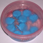

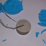
The ceramic pill
inside the capacitors were 6 mm thick and had 22 mm diameter.
It seemed uneasy to erect a laser with the plasma column 20 mm wide, so I
decided to cut the ceramic pills into pairs of halves. It was done by hand
engraver tool with a diamond cutoff disc. Then the obtained semicircles
were put along a straight line to form an elongated shape:
      --
  |)   ^
  (|   !
  |) ~150 mm
  (|   !
  |)   V
      ---
 >--< ~10 mm
A pair of such electrodes was installed into a laser with a Lamberton-Pearson
type of preionizer (i.e. with wires stretched along the electrodes). The
interelectrode spacing was set to 4 mm/ The laser was installed onto a usual
(low inductive) frame having storage capacity of 4 nf (2 of muratas). Here was
no success in obtaining a volumetic discharge. Neither with air:CO2 mixture nor
with N2:CO2 one. There was multitude of sparks but no violet glow.
The electrodes were then moved into a laser with spark type preionizer
(being referred here like "classic scheme"). The design of the laser was a bit
different from the described above, but the main parameters (like distance to
preionizers or their capacity) were kept untouched. There appeared difficulties
with a sliding spark from electrode keeper, along the ceramic surface and to
preionizer pins. (One should keep in mind that the sparks along the surface
of something with high dielectric constant can easily become very very long.)
So the electrodes were put into epoxy compound (its obvious, that the facial
surface was kept clean and open).
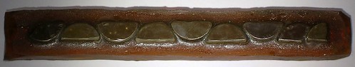
This helped to suppress the shortening
breakdowns, but the volumetic discharge still was absent at athmospheric
pressure. Neither with air nor with nitrogen. With the epoxy protected
electrodes the electric strength of the laser raised to the extent that allowed
tests with reduced pressure.
At 900 mbar (90% of the normal air pressure) a strong violet glow appeared
between the electrodes. No the rain of sparks didnt disappear. But at the
background of it there was a strong volumetic discharge.
After installing into a resonator and proper alignment the lasing was
obtained. However despite all expectations it was weak and unstable. The energy
was ~ 1 mJ, and the probability of lasing was ~10%. Judging from the
comparatively high output energy the instability was due to discharge
instability rather than due to the proximity of the lasing threshold.
CONCLUSION: the distributed impedance of the electrodes (their effective
resistance) created by the specific capacity of 526 pf/sq.cm. has appeared
to be too small to stabilize the discharge. The surface capacity was increased
by 30 times in comparison with mylar, but it brought not only the rise of the
energy deposition, but also the rise of plasma instability.
If one wants to advance in this direction I would advise to increase the
ceramic thickness by three times (to 15..20 mm). However it will possibly
require profiling of the electrodes.
This laser appears to be kinda expensive and the result is "kinda
disappointing".
ABIT OF UPDATE
↑
The things, being described in this part, were done in 2015. However it was not
uploaded into this report, just due to the fact that I have only one pair of
hands.
The results, given by the capacitor laser, are miraculous from the point of
view of pure science. On the other hand, they are not very impressive from
the point of view of practice. Since that it was decided to return to the
carborundum. For that moment the lasing was obtained with only one type of
carborundum bricks (the ones for the knife-grinding machine), and it was
interesting, how would the laser behave with other types of bricks.
Multiple long searches in the neighbour supermarkets had yielded nothing.
All the bricks, being sold there, appeared to be non-conductive. Including
those ones, with clear sign on their package, that said, that those bricks
were made of "silicon carbide". Most possibly it was alundum. Aluminum oxide
is much cheaper and they use to sell it under the name of SiC. In order for
not to buy waste things it was invented to test the bricks by an electric
stun gun already in the shops.
That baldness bothered sellers, but they could be convinced that it as just
an "anti-scum check". It was needed to have a "true" conductive carborundum
brick with oneself, to demonstrate the sellers "how it should really look like."
So, hardware stores and supermarkets appeared to be useless. On the contrary,
the common street markets were a bit better. I was able to dig out a few bricks
with the necessary conductivity. But there was another problem. In the street
market it is hard to purchase the things in necessary amounts. The laser needs
at least two electrodes (larger laser needs more of course), but the sellers
typically have one brick, or several ones, but with different size and shape.
Finally the bricks were ordered via the Internet. Those were Russian SiC
abradant bricks of "63C" and "64C" types. The length of bricks of both types
was 100 mm, and their section was nearly square: 9 x 11 mm.

When ordering via the Internet the buyer can not test the product before
buying. And, because in our case the property of the brick to conduct
electricity does not affect its abradant properties (at least they think
so) You can not return the faulty thing.
The results of testing are following: both types of the bricks are able
to conduct the electrical current provided that the applied voltage is high
enough. The bricks of "63C" type (bright green, medium and fine grit) conduct
current worse than the bricks of "knife grinding machine", the laser has
already worked with. The bricks of "64C" type (dark green, rough grit) conduct
current even better than the bricks of "knife grinding machine". I'll say
here in advance that I was unable to get any lasing from the "63C" bricks.
Even after attempts to reduce their resistance by doping with carbon (by
dipping them in drafting ink and annealing at high temperature).
The low resistance bricks were installed into a system with spark
preionization (see above, part "sparkie") having a length of one brick. In
this system the bricks allowed to get lasing at electrode-to-electrode spacings
between 3.5 and 4.5 mm. Up to 3 mJ were obtained with low impedance pulse
forming network and up to 2 mJ with a high impedance one (based on mylar rolled
K75-14 capacitors). Here i must specially emphasis that the laser not only
worked with a high impedance circuit, but it had SURVIVED after that. It was
returned to the low impedance circuit and continued to operate (for virtually
unlimited time).
However the discharge stability was much worse with the new bricks (64C) than
with the old ones (the ones from "knife grinding machine"). Even with a low
impedance feeding circuit the discharge column contains too many streamers,
and each third/fifth pulse is with a bright spark only. There was a thought
that in a system with Dumanchin's type of preionizer the discharge would be
better, but in reality the laser of Dumanchine's type did not lase at all
with the new bricks.
It was supposed that the new bricks (64C) have too low resistance to
stabilize the discharge properly. And a combined system was made. Generally
it is the same "sparkie" but the bottom brick (cathode) was of the old type
(from a "knife grinding machine") and the upper brick was of the new type
(64C). The cross section looks like that
    NEWNEW
    NEWNEW

    OLDOLD
The result was fairly good. The laser is operational with the spacing between
the electrodes of up to 5.5 mm. The discharge is visually very uniform, without
any streamers. Below is given the dependence of energy in serial pulse to the
spacing in the main spark gap. Under the term "serial pulse" I mean the average
pulse in series. Not the first one, which apparently is bigger. Also note
that the spacing in the main spark gap does actually determine the charging
voltage of the main storage capacitor (or battery of capacitors).
| spark gap setting |
Peltier reading |
rep rate |
laser output |
| 11 mm |
6.5 mV |
10.2 Hz |
4.01 mJ |
| 12 mm |
9 mV |
9.4 Hz |
6.12 mJ |
| 13 mm |
9 mV |
9 Hz |
6.4 mJ |
| 14 mm |
9.5 mV |
8.2 Hz |
7.4 mJ |
| 15 mm |
9 mV |
7.6 Hz |
7.6 mJ |
The second column contains the readings of a homemade Peltier calorimeter.
Its calibration ratio was (as You could remember) 6.4 mW/mV. I should also
remind that the specific voltage of the spark gap breakdown was 2.6 kV/mm.
It means that the result of the last row were obtained when the storage caps
were charged to 39 kV. The laser was filled with air with CO2 mixture with
the ratio of 1:1. A droplet of xylene was added to a full automotive tyre
of gas mixture. "A little" means something like 2-3 cubic millimeters.
Another way of chimera making was to combine one metallic electrode with
another carborundum one. It was clear that it was senseless to install a
64C brick into the scheme, because even two bricks of this type have not enough
resistance to stabilize the discharge. Therefore a "high ohmic" brick of 63C
was used in pair with a full metal electrode. The last one was sawn out from a
4 mm thick aluminum stripe. It then was carefully smoothed to Chang's profile
and polished. This laser has barely lased. At N2:CO2 = 1:1 mixture the output
in the best pulses was up to 2 mJ. However it was unstable. Most of the pulses
were without lasing. In many cases there were breakouts around the carborundum
brick.
It was finally decided to make a new tube, having a length of two bricks.
In order to suppress the regular flashovers from the main laser electrodes to
the preionizer, and for easier production too, the design of the tube was
changed. Here is the draft:

And here is the photo of the new (for that time) tube:

Preionizers are made of M3 bolts, having been screwed from inside a plastic
sewer tube with 2 inch diameter. The gaps between the heads of the bolts inside
the tube form the spark gaps of the preionization. From the point of view of
flashover prevention it was the best to position the upper row of the bolts
directly in the plane of symmetry of the tube, and to displace the lower row of
the bolts downwards a bit (see the picture above). The spacings in the spark
gaps (between the heads of the bolts) were ~1 mm.
Each of preionizer spark gaps is fed through an RC circuit, consisting of
(wirewound) 5.6 kOhm resistor of C5-37 type and a high voltage ceramic KVI-2
capacitor of 100 pf. (Sometimes there were used 68 pf, but without any
significant change in performance.)
The resonator's back mirror was concave, aluminum on glass (the old good
automotive rearview mirror having been washed out from its protective paint).
The front mirror was Znse plano, 15% transmittance.
Storage bank had 8 nF of capacity (4 doorknob Muratas 2nf x 40 kV each).
The laser got a run on a mixture of automotive exhaust gases with technical
grade carbon dioxide in proportion of 1.5:1. Yes, You can believe Your eyes.
The modern automobiles with injection type engine have authomatic adjustment
of fuel mixture to provide the remaining content of oxygen in the exhaust gases
at the level not exceeding 1%. Therefore the authomotive exhaust gas is a
promising thing for home use in place of pure nitrogen.
So the laser got a run on a mixture of exhaust:CO2 = 3:2. At the repetition
rate of 6.4 Hz it gave pulses with the average energy of 24 mJ. At 1 Hz it
did nearly 40 mJ. When focusing its beam on a surface of some clay flower pot
one could see a spark in the air from time to time. I.e. the spark was not
on the surface but in front of it. Generally any surface, being placed into
laser beam beyond its focal point, makes it easier to ignite the spark in
the air. Maybe it is the dust from the surface, that helps the process. And
for some reason at least in my experiments, exactly clay surface makes it
easier to the most extent.
In order to upload the video of this tube in work I was to make a
video session at present time (2019). At the time described (2015) the video
had not been taken.The tube has barely survived the 4 years of
storage. It was needed to make new mirror mounts (old ones, made of plexiglas, have cracked), to resolder the electric connections (old solderings have darkened due to the time passed), 3 RC preionizer circuits were completely replaced). And of course cleaning.
From the retro-data above I've made two main conclusions:
- Not any or every brick is suitable for the laser. Therefore it is too
early to make a special guide, despite the design is very easy to create
and performs fairly well.
- There exist an optimal resistance of the electrodes, when laser operates
best. Too low of the resistance does not stabilize the discharge, and too
much of it causes the lack of energy.
INTERLUDE THEORETICAL
Let's try to determine the necessary resistance of the electrodes, We will
start from two suggestions.
Suggestion 1: The more is the resistance of the electrode the better is the
stabilization. Note that the increasement of the resistance does not cause
decreasement of the energy deposition in gas. Indeed, if the voltage drop on
the discharge is known and equal to Ugas, if the value of the storage capacity
is Co and if its charging voltage is Uo, then the energy deposited in the gas
will be: Qgas = Co*(Uo-Ugas)*Ugas. We also know that the energy stored in the
charged capacitor can be expressed as Co*Uo^2/2. Finally the dissipated energy
will be Qdiss = Co*Uo^2/2 - Co*(Uo-Ugas)*Ugas. Note that neither useful nor
dissipated energy does depend to some "ballast" resistance.
Suggestion 2: It is obvious that with the increasement of the ballast
resistance (the one connected in series with the laser discharge) the
conditions of lasing become worse. At least due to the fact that the time of
the energy deposition becomes longer than the lifetime of the upper laser
level.
The second suggestion means that for the good laser performance it must
be true that Rb*Co < tauUL, where Rb is the value of the ballast resistor,
tauUL is the lifetime of the upper laser level
(~1 mcs for CO2 at atmospheric
pressure).
Let's designate the specific capacity for the unit of surface of the electrodes
as c = Co/S and the specific resistance of the electrodes for the unit of their
surface as r = Rb*S. (S means the area of the electrodes, or the cross
sectional area of the discharge, if You wish).
In this terms the previous condition may be written as:
Ro*Co < tauUL <=> c*S*r/S < tauUL <=> c*r < tauUL
If we recall that in our experiments we have storage capacity of 4..6 nF for
the electrodes sized 1 x 10 cm, i.e. c = 0.4..0.6 nF for each square cm, we
can get the numeric estimation:
(0.4..0.6)*1e-9[F/cm^2]*r[Ohm*cm^2] < 1e-6 sec
so r = 1.7..2.5 [kOhm*cm^2].
The value we got is the result we looked for. The exact equality sign instead
of the inequality appears due to the 1st suggestion.
THE REQUIRED SPECIFIC RESISTANCE OF THE ELECTRODES SHOULD BE
r = 2..3 [kOhm*cm^2]
Note that this is a sum value for BOTH electrodes
From this formulae it follows that for high load lasers, having more storage
capacity per unit of area of the electrodes, one should take the electrodes
with lower resistance/ And vice versa, for low load lasers, having less storage
capacity for the unit of area of the electrodes, one should take highly
resistant electrodes. In the reality, however, the things are a bit different.
High load lasers usually have no problems with reaching the lasing threshold,
but have serious problems with the discharge stability. On the contrary low
load lasers have much better stability and allow to decrease r a bit to avoid
troubles with reaching the threshold. You see, that the estimated value of
the optimal r is just a reference point. In any case the required value of
the resistance should not be very different from a few kiloohms for each
square cm of the electrodes. And one should decide, the correct deviation
from the reference point in each case individually.
Another note. The taken value c = 0.4 .. 0.6 nF per square cm corresponds to "common" lasers with the charging voltage Uo~30kV, discharge voltage drop of
~15 kV, interelectrode spacing of ~ 5 mm (counting by air). For lasers with
higher working voltages the same milliCoulombs per square centimeter may be
achieved at less capacities. Indeed, if for the matched mode of operation we
choose the charging voltage to be twice of the voltage drop on the discharge
gap: Uo = 2*Ugas, then q = c*(Uo/2), and further on, with the increasement
of working voltage, the necessary capacity decreases in reverse proportion to
the voltage. The allowed value of the ballast resistance does of course
increase in this case.
Further if the thickness of the electrodes rises in direct proportion to the
voltage (which is reasonable from the point of view of electric strength) then
already the volume specific resistance should be constant, not the area
specific one.
And finally, if we designate the volume specific resistance as ro and the sum
of thicknesses of the electrodes as h, then
ro = r/h = 2..3 [kohm*cm^2]/1 cm = 2..3 [kOhm*cm] or ro = 20..30 [Ohm*m]
This is nearly twice as high as it was derived in [6] from very other propositions.
In 2019 I made an attempt to purchase a new batch of the bricks from knife grinding machine, the laser liked so much. However the old sellers weren't online. After long search I've found new bricks, having the same shape, size and similar color. Buying and testing have shown that the new ones are completely dielectric. And it seems that they are made of corundum, not carborundum.

12.12.2019
3D PRINTED LASER
↑
Looking for suitable materials for the electrodes with distributed resistance
have lead to a comparatively new one - to conductive ABS plastic for 3D printers,
or CABS. A 10 meters long sample of CABS filament was ordered. As it had been
estimated, it was to be enough for a test in a small laser.
Such a laser was modeled and created. Its electrodes were made of CABS and had
100x5x10 mm size. Their profile was made according to Chang's formulae for
4.5 mm of spacing between the electrodes and with the factor of curvature of
0.04.
Here is the photo:

And here is the stl model: electrode.zip
The holder of the electrodes was made of common PLA plastic:

and here is the stl model of the holder: 3DPframe.zip
There are 12 holes by each side of the electrodes. A cuts of CABS filament are
to be inserted into these holes during the assemblage of the laser, so that
between the ends of the cuts there appear 1 mm gaps to form the preionizing
spark gaps. Initially the spacing between the electrodes was set to 4.5 mm,
according to the previous calculations.
Here is how the gas discharge unit looks like when assembled:

Further on this assembly goes into a piece of 2" plastic tubing, having some
conductive terminals. The ends of the tubing are covered with mirror mounts
as usual.

The laser got a run on N2:CO2 = 1:1 mixture. The back mirror was aluminum and
the front one was dielectric on Znse having 92% reflectance. Storage capacitor
was 4 nF. The spacing in the main spark gap was from 7 mm to 11 mm.
The laser was even able to lase. Its power and stability were similar to the
short variant of the mylar capacitive laser (see in this text above). Frankly
speaking it gave too little, despite the fact, that its discharge was very
clean: no sparks or streamers were visible even when the tube was filled with
air.
Observing the discharge column through the end of the laser (using a protective
glass of course) has shown that the width of the discharge did barely reach 3 mm.
Three millimeters are usually not enough for carbon dioxide laser due to large
diffraction losses (the losses of the diverging beam in a resonator of limited
aperture). Apparently the factor of curvature for the Chang's profile was
choosen too high (it was taken almost at random, just as a value seeming to be
verisimilar). It was late to print another electrodes however. The plastic had
ended.
In order to widen the discharge column the electrodes were filed from the face
side. About 0.2 mm were milled out. The laser began to work better. The width
of the discharge became 3.5 mm and it was possible to observe rather long
series of pulses with lasing at 1 Hz rep rate.
The electrodes were milled further. It was planned to take 0.2 mm of the
thickness from each electrode again, but a mistake of processing had lead
to that it was taken 0.2 mm from one electrode and 0.5 mm from another one.
The width of the discharge had reached ~5 mm after that. The discharge was
still uniform and clean. Nevertheless the laser had dimmed out. Neither
careful alignment nor varying of spacing between the electrodes have helped
to get lasing.
The discharge column with section of 5 x 4.5 mm is surely enough for this laser.
In other systems with these sizes it was rather easy to get powerful lasing. It
means that this laser starves for the current. Apparently the resistance of the
electrodes is too large. When the discharge was narrow, the current density was
barely enough to reach the threshold. And when it became wider the current
density became too low.
To lower the resistance one can reduce the thickness of the electrodes. But it
should not conflict with their proper profile. So a trench was milled on the
back side of the electrodes and its depth was selected so that the remaining
thickness of the plastic was not less than 2 mm. The trench was filled with
aluminum foil in the laser when assembled.

During the very first test the electrodes were broken out - the spark made a
charred hole in both of them. Obviously there was no volumetic discharge
after that.
- P. Pace, P. Mathieu, J. Cruickshank. Miniature, sealed TEA-CO2 lasers
with integral semiconductive preionization. Rev. Sci. Instrum. 53 (1982)
No. 12, 1861-1863
- D. Beaupere, G. Helias, A. Bettinger. TEA CO2 laser with a SiC anode.
Rev. Sci. Instrum. 56 (1985), No. 12, 2251-2258
- A.I. Pavlovsky, M.A.Voinov V.V.Gorohov et.al. Transversal spatial
structure of high voltage diffusive discharges. Journal of Technical
Physics, Vol.60,N 1, 1990, pp 64-71
- V.Y. Baranov, V.M. Bporisov, Y.B. Krokhin et. al. Free Running Stimulated
Emission from an Electric Discharge CO2 Laser in the Nanosecond Range of
the Light Pulse Duration. Sov. J. of Quantum Electronics, v5, N5, 1978,
pp 1141-1143
- Jon Singer. TJIIRRS: Number 5C [New] of an Ongoing Series; “Theorie und
Praxis IIA”: Revamping the “DKDIY” Laser Part 1.
- T.W. Johns, J.A.Nation
A Resistive Electrode High Energy Transverse Laser Discharge. Rev.Sci.Instrum
44, No 2, 169-171, 1973
<< HOME PAGE |


