|
Nitrogen laser operates on transitions of second positive system of.... blah...blah...blah... All this junk is not required
to make a laser. This type of laser is attractive due to the fact that it can be constructed with resources all easy to get.
You will not overheat Yuour brain by the queations like 'where to get ruby' or neodimium glass or rare and DEA controlled dyes.
You won't need rare mirrors and twisted alignment. The laser is superradiant i.e. works mirorrless. At last it operates
in the ultraviolet range. Practically this is almost as good as if it was in visible - many things are luminiscent under
UV so the laser spot is easily observable. (That cannot be said about CO2 laser - until it burns something You never know
if it operates at all.)
This laser or either its design aren't invented by me. The guide is made by steps of the one at http://www.sparkbangbuzz.com/tealaser/tealaser7.htm
For a while I thought that sparkbangbuzz's guide is perfect and there's no need to translate my version into english.
However after a long time of work with gas lasers and high voltages a new step of understanding came, so some new information
appeared in this guide that may be interesting for english-speaking people too. Never say "never", lol.
I. Resources.
We will need:
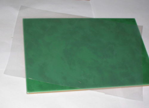
- Something plane and hard enough (for basement). The sizes of the plate should be about of A4 printing format. I've got a glased tile 200x300 mm sized.
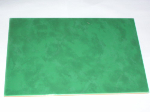
One could also take a thick textolite sheet or (even better) a plane sheet of iron (it is handy to use magnets to attach all things to the iron). Don't use wood. It is very unstable when humidity changes.
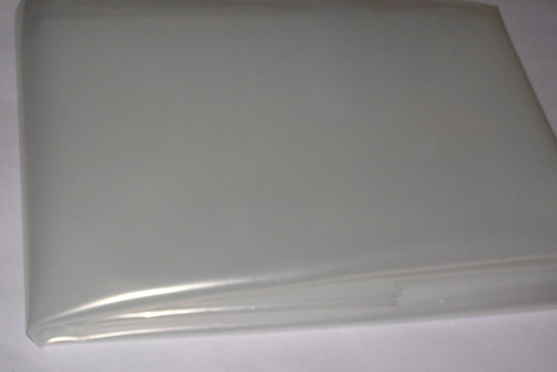
- dielectric foil (film) with thickness at about 100 mcm,
One may use transparent printer sheets, garden polyethylene (fresh one is better), overhead plastic, etc... etc...
The best choice is of course th mylar (can easily be found as laminating pouches), however this guide will be oriented
to the 'poor man's solution' utilizing polyethylene sheets. When the foil is unknown, You should measure its thickness
beforehand.
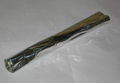
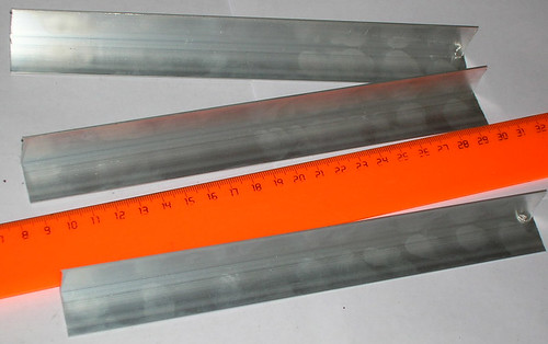
- fresh (clean and level) aluminium angle stock (better when directly from the shop). The required amount of the aluminium
angle should allow You to cut three pieces 20 cm long each. Side of the angle should be 15..25 mm, wall thickness 1..1.5 mm

As the experience shows, the aluminium angle stock is the most hard to get part. If You have one, the rest will be easy.
Also I should note that it is almost impossible to say how to replace it in case if You can't obtain it. Later, when You
became a bit experienced with this kind of laser, You will see thousands of things around You, that can be used as electodes.
However when building this laser for the first time don't try to make proposals. Typical mistakes are: steel school rulers
or hacksaw blades - both are unusable.
- kitchen aluminium foil
the thicker the better
- aluminium duct tape (40..50 mm wide) Of course You may avoid it and use only kitchen foil. But with sticky aluminium strips all becomes easier.

- power supply rated at above 6 kv (easy check - it must be able to give 8 mm long spark between pins)
You can obtain one by:
- scavenging from an old laser printer (where it is used to charge printing drum)
- extracting a horizontal trace generator from an old tv set (the CRT one, not LCD type)
- or get and decompose a household air ionizer
- or use a board from a plasma-ball souvenier (don't forget to add a rectifier to the output of its flyback transformer)
- people also use he-ne laser power supplies, those ones produce 10 kv output when open-circuited (to ignite the laser tube)
- use ignition coil and halogen lamp electronic transformer (that type of power supply is described in another guide at this site)
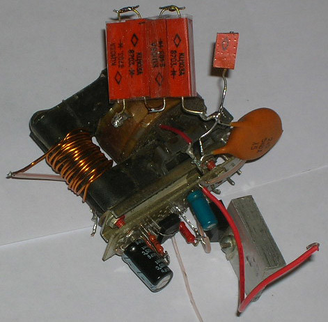
- nd certainly You can build a power supply by Your very own schematics. An example of the schematics is shown on the picture below.

One more note. If You are going to feed the laser by an electrostatic machine be sure to take all measures
to eliminate corona discharge. The electrostatic machine gives output barely enough to feed an air laser
with rude design (in most cases just not enough)
The power supply may look like that:
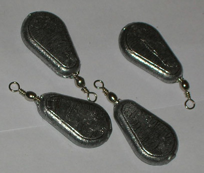
- some weights (or magnets if you do assemblage on a steel sheet).
The weights should be rather heavy (20 g or above) otherwise You will not be able to make good contact.
- Resistor rated to 10 kOhm or more. The resistor should be able to endure feeding voltage. In the simpliest case choose rather high
power one. 0.5 W should be enough if dry or 0.25 W if varnished.
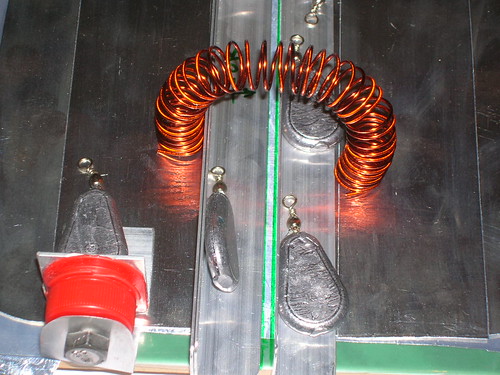
The resistor can easily be replaced by an induction coil (see pictures a bit further below)
- Resistor (ballast) rated to 300 kOhm or above
This one will be used to limit the laser's repetition rate and also will protect power supply from shortenings and voltage
shocks which appear extensively when laser works.
- White (very white) paper. It will serve as visualizer of UV light. If You have no sheet of bright white paper (like datacopy(tm))
then use any other paper, however You have to paint it with a fluorescent marker.
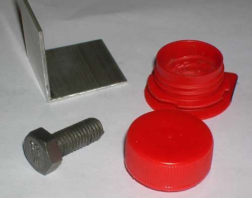
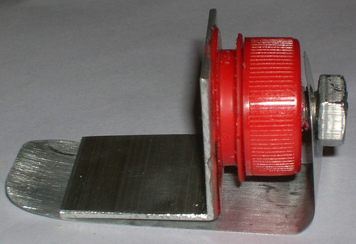
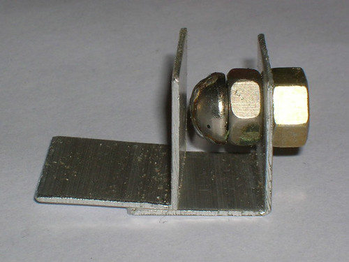
- Plastic bottle lid, piece of 30x30x30 angle, M8 screw, and a nut to pair with it. This stuff will become a spark gap in future.
We will also need the next tools:
- Scissors
- Metal working hacksaw
- Fine grit filer or sandpaper
- Screwdriver with a large dielectric handle
- ruler
- marker
- a glue (fast curing epoxy one is best)
II. Assemblage.
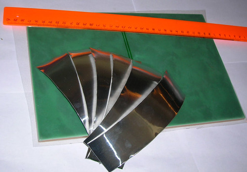
- Using the hacksaw cut 3 pieces of aluminium angle stock, 20..21 cm long each.
Those will be the laser electrodes. IMPORTANT not to defrom the angle stock. Saw it slowly and with only soft hits. It is
also important not to make scratches on the working edges of the electrodes.
- Round the sharp corners with the filer.
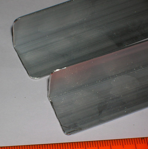
Don't touch anything in places where You did not saw. It takes only one filer hit for the working edge to become unoperational. Yes You can
bring it to life. By means of fine grinding on a flat glass plate... But it takes long, it's hard and boring... It's simplier to make a new one.
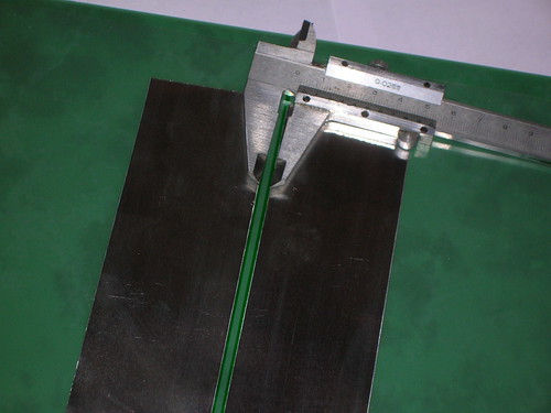
- Cut a polyethylene piece, sized to fit the laser basement (in our case - equal to size of the glazed tile.
Mark it - near the middle draw two parallel straight lines, spaced by 3..4 mm from each other.
- Cut (with scissors) six equal pieces of the aluminium duct tape, 17 cm long.
The foils of laser's capacitor should be by 2..3 cm shorter than electrodes - it helps to supress the sparks at ends of the electrodes.
Those sparks are usually very annoying.
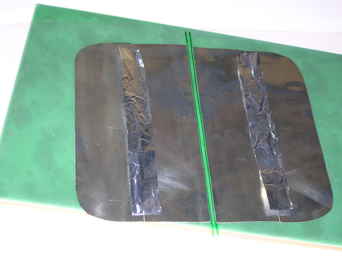
- Turn the polyethylene for the drawing be underneath. (In order to marker's dye not to char, and to avoid flashovers throug those
charrings.) Stick the first two strips of alunminium duct tape parallel to each other with a gap of 3..4 mm. Thats where the marks come
in use.
ATTENTION! The gap and parallelism are critical!. In principle the laser does work with
gaps from 2 mm to 6 mm and when the foils (but not the electrodes) are unparallel up to ~2 mm per their length. BUT. Maximum power
will be only with gap lying between 3mm to 4mm and when it is equal all along the electrodes. Too wide, too narrow or slopped gap
will drastically reduce laser output. Further reading will make it clear why it happens.
In principle one can make top plates (wings) without using the aluminium duct tape, just using the kitchen foil. But
- It bugs to adjust the spacing between foils anytime
- The foil lies non uniformly, that leads to more often breakdown of the polyethylene
I tried many combinations: upp and down - sticky aluminium, up - kitchen foil bottom - sticky aluminium, up and down - kitchen foil
up - sticky down - kitchen foil. Better resultsa are when aliminium duct tape is up and kitchen foil is down.
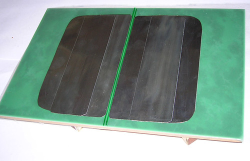
- Extend wings by sticking another aluminium strips.
Wider than 10 cm is senseless - laser would not light brighter. Further on it is needed to make an electric contact between aliminium
strips in pairs. It seems to be simple to stick another strip above. However the glue on the aluminium duct tape is dielectric. And even
when it easily breaks down under the feeding voltage of the laser, the repeated sparks provide heat enough to melt polyethylene.
Such laser works but degrades easily. In order to avoid it we'll make better contact.
Let's cut two strips of kitchen foil 1.5..2 cm wide and 16 cm long. Put them over the places of future contact.
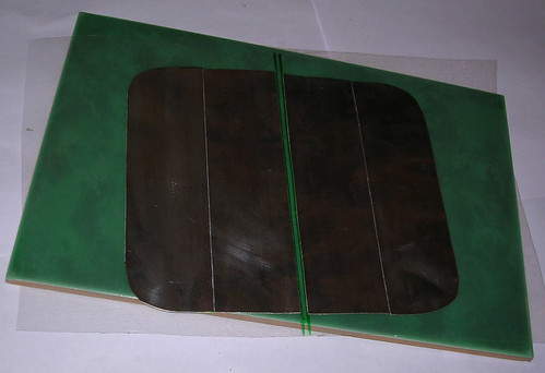
Press them and stick aluminium duct tape above. You will get this:
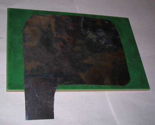
- Cut the lower plate from the kitchen foil. (Or either it may be named as "grownd plate" or "common wire".) It sizes should be nearly
the same as the upper wings contour has. (Maybe a bit larger to avoid voltage overstress at edges.) The corners should be rounded.
Also leave some lead for power supply connection. Flatten the foil on the laser's base plate.
- Put the polyethylene leaf with the upper wings over the bottom foil.
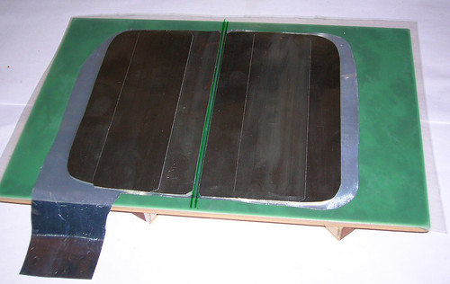
Take one of the (three) ready electrodes. Put it above one of the top foils setting the vertical side of the angle towards the
inner side of the foil (towards the gap between wings), press it with weights and align the electrode carefully along the
edge of the gap between wings.
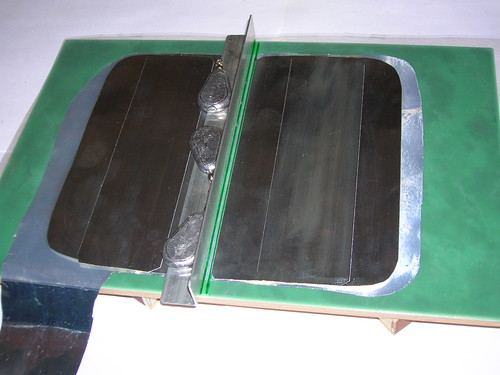
Let's assume that this electrode should always be aligned aling the wing (inner) edge and we won't displace it during any tinings.
Take two rest electrodes, put one into another to get a "doulble L". And place this assembly over the wing, that remains free after we've
set the other electrode. Load it with weights and align along the gap.
Don't bother now about careful aligning of this electrode. It will be done at the stage of laser tuning.
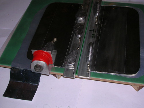
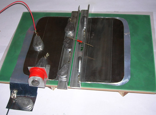
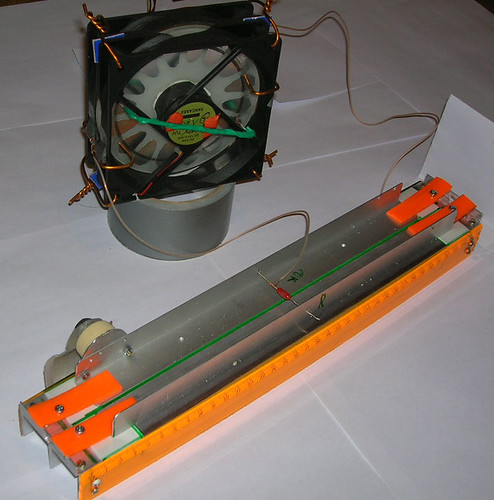
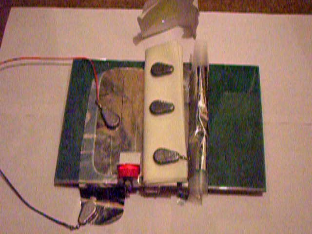
The electrodes should be placed as shown on the picture.
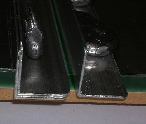
Note that the right (on the photo) electrode forms a"wall" aligned to a side of the gap between top wings. And the left electrode forms
a "blade" turned towards the wall. The blade is set at ~1 mm above the dielectric with a help of auxiliary aluminium angle.
- Let's make a spark gap. Take a piece of aluminium angle 30x30x30 and glue a plastic bottle lid to there. Or even better glue there not
the lid itself but that part of the bottle, where the lid is screwed. Make the end of the M8 screw to be round. (Ball type spark gaps have less
discharge length and thereafter have the less resistance and inductivity. Take a strip of aluminium from a beer can to make a wide lead.
You may even fold the kitchen foil to make multilayer shim. Width of the strip should be not less than 15 mm to provide low resistance
and low inductance. Make holes (6mm in diameter) in both plastic lid and contact strip. The M8 screw will itself make the other work on
threadening these parts, when You will screw it in.
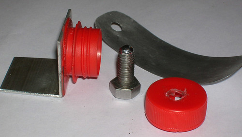
The assembled spark gap will look like this:
Certainly one could use a more simple discharger:
However the open spark gap cries out too loud. You may feel it enjoyfull at first. But later on You won't like it too.
That's why we make not just a simple air laser, but air laser with muffler.
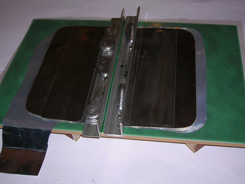
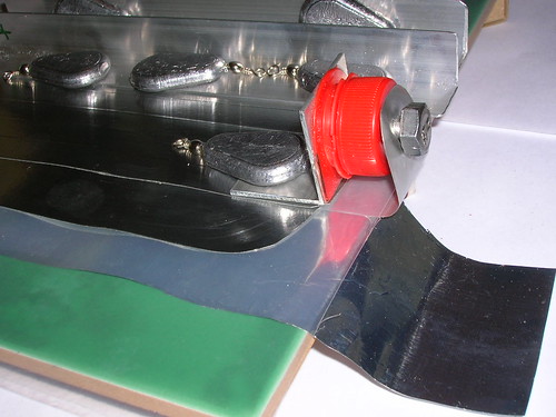
- Set the spark gap as so its foot stays on the top wing of the laser, and its bending tail goes under the polyethylene and lies on the
bottom (ground) foil
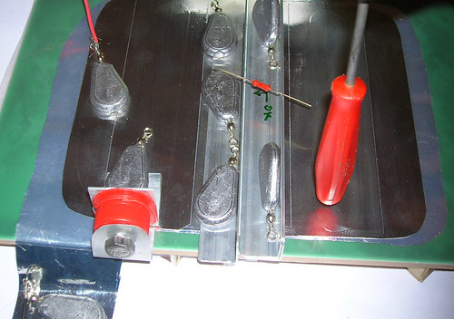
- Attach laser to high voltage power supply. It's suitable to use loads instead of alligator cilps in order not to damage thin foils.
Put Your high voltage resistor between laser electrodes.
You will obtain this:
Sometimes they use and inductance coil to make contact for the direct current between laser wings.
For example like this:
- Carefully set the distance between electrodes at 2mm. Keep an eye for not to displace the "wall" electrode. As it was noted above
it must always be aligned to the edge of the gap between wings.
Set the spark gap to 1 mm sparklength. You may use the next sequence of actions: screw the bolt until it touches the metal wall. (If You
don't feel or see this, You may use a multimeter (having been set to ohms measurement) to detect fact of touch.) Then unscrew the bolt
back by 1..1.5 turns. (If You use not M8 screw or its thread is not standart the number of turns may vary.)
Thats all with assembling. Time to turn the device on and tune it up.
III. Tuning.
The 'mature' lasers usually have mirrors to be aligned. It's pity, but our "airgun" has also something to align. That's the electrodes.
SAFETY REMINDER: If You use a low power unit with a small flyback transformer, and if it feeds from 12 volts
then the probability to die from electrocution is not higher than probability to die by flu. BUT IT IS NOT ZERO!
On the other hand if You are using a powerfull source (like microwave oven transformer with a voltage multiplier)? then every uncarefull
approach to high voltage parts - and You're finished. You don't even need to touch. There can jump a spark and hit deadly.
For safety reasons I recommend You to use a low power voltage supply. Remember that voltage itself does not kill. The electic current kills .
Then attach laser to voltage supply. Use a ballast resistor to limit the feeding current and repetition rate of the laser. Very low power
units resistive to shortenings (such as electrostatic machine) may be attached directly - without a ballast.
The electric scheme of laser is given below in part with comments.
- Switch on the laser. (Turn on the high voltage.)
Adjust the gap in discharger for the repetition rate (as You hear it) to be at 50..100 Hz.
YOU MAY TURN THE SPARK GAP SCREW ONLY WHEN HIGH VOLTAGE IS TURNED OFF!!!
- Wacth the sparks in the laser gap. Usually it is either absent at all (the electrodes are too far from one another) or a bunch of sparks
concentrates near one of the ends.
To adjust the electrodes You will use the screwdriver with a large dielectric handle. Keep it as a pendulum, make soft easy hits to
move electrode towards another one.

Sparks zone will begin to creep towards the side where You hit.
When the sparks will become spread almost uniformly along the electrodes and when they will coexist with uniform purple glowing, it now abot
to lase. Take a fluorescent paper - visualizer and place it near one of laser's ends. It's unpredictable what end will emerge the ray for the first time.
When laser works correctly one should see uniform purple glowing in the laser gap along with rather weak sparking, also uniformly distributed over the
electrodes.
If the glowing does not want to appear (You see sparks only) It means that the (laser) gap is either too narrow (less than 0.5 mm) or too wide
(over 2 mm). If the purple glow still does not want to show itself (at any gap widthes), it meands that the electrodes are too dirty or
scratched. One should discard such electrodes.
When the laser gap glows correctly place the visualizer paper opposite one and another laser ends. Surely You'll find the laser spot.
Usually it has a form of small bright point in the place, where a shadow of laser electrodes falls onto the paper.
When laser spot is found, tune the laser to maximum output using very tender hits to electrodes. The spot will grow in area and brightness.
Don't forget to watch the laser spot at both ends of the laser. Sometimes the spot may "creep" to another side during tuning process.
If the spot refuses to appear, try to decrease the laser gap (keep an eye for not to kill the purple glow) and increase voltage
(by increasing the sparklength in the spark gap).
Voltage increasement should be done VERY gradually. The laser operates near the breakdown threshold of the polyethylene film. In case of
failure You will need to remake the wings of laser.
SCREW THE SPARK GAP ONLY WHEN HIGH VOLTAGE IS TURNED OFF!!!
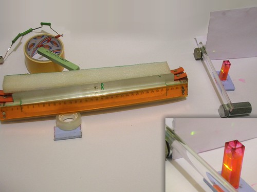
- Well tuned laser gives bright fluorescent spot ~1 mm sized on a paper near the laser. The spot should remain clearly visible
when having sizes 2x5 cm (5 meters apart from laser) even in not darkened room
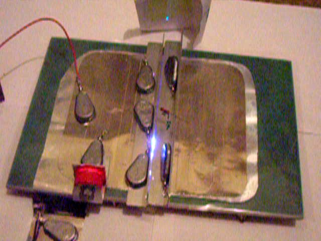
It is a pain to photo the woking laser, because it does not light most of time. It flashes only 50-100 times per second. The chance it
burst exactly when camera shots is almost zero. And I've got no laser-to-camera synchronizing circuit yet. Therefore I use the video
mode and salvage frames from the movie. It defines lower resolution and lower quality, sorry about this.
IV. Silencer.
In tuning process You have probably already noted that laser sounds loudly. This sound is enough to summon Your neighbourers if You
live in multi-quarter house. Enclosure of the spark gap almost halves the sound but not eliminates it.
The discharge in the laser gap is noisy itself.
In order to gain some more time for laser operation without attracting ill attention of surrounders we should make a kind of muffler for our laser airgun.
Take some sponge material, felt, polyfoam or any other sound insulation dielectric substance.
Make a cover for the main discharge gap. If the material is thin - use several layers (not less than a centimeter total).
Carefully (in order for not to break the alignment) put the cover above the electrodes and press it (the cover) by loads.
If the tuning remains unchanged, the silenced laser shines almost as brightly as it did without a muffler. But less noisy.
Usually the silenced laser does not become suffocated. However if Your laser shows power decrease - try to use less dense material
for the cover.
Thats all. Laser mock up is ready for entertainment.
For the constant use, I offer You to work out a more stable design.
V. Comments and specialities.
- Schematics of the laser.
Here are two variants of scheme of this laser
 
The first one represents wings of laser as capacitors and the other one - in form of delay lines. The first scheme describes low frequency
behaviour of laser. The second one tends to describe high frequency characteristics.
For the laser to be optimal it is needed that Rá>>R1, then wings of laser will be equally charged.
It is also needed that R1C2>>1ns. It is easily obtainable when R1 is several tens...hundreeds of ohms. Since that even at high repetition rates
the resistor dissipates not much of heat so the real nececcity to replace it with induction coil is only aestethic intentions.
R6 regulates rep rate (at least in theory) frep: Rá=1/(frep(C1+C2)).
When foils are 10x20 cm and polyethylene is 0.1 mm thick C1+C2=8000 pf.
Rá needs to be 1.2 Megaohms for 100 Hz repetition rate. (In the reduction to practice it usually has lesser values, due to power supply
internal resistance, due to different kinds of leakages and so on.) The repetition rate does also strongly depend to the ratio of
power supply voltage to the spark gap breakdown voltage. If they are nearly equal the rep rate is low even with small ballast resistor.
The spark gap should have lowest possible resistance when switched on, high speed and good stability. All those properties (except
maybe stability) are obtainable when the spark has lowes possible length. Thus the discharger should be designed as ball-to-ball
or ball-to-plane. Sharp edges and pins should be avoided.
Concerning the high frequency operation of the scheme, there ia a lot of misunderstanding in articles and internet posts. Afew ones say
that the laser ha Blumlein like circuit and transmission lines begin to form waves when the spark gap fires. Others say that it works
like LC-inversion circuit and one may treat wings like capacitors. But most ones forget the way how the main laser gap affects the
RF properties of the circuit. Practically it may be treated as 'nano-inductive' 'super-mega-fast' sharpening rail discharger included
into the low impedance transmission line formed by wings.
When the spark gap P1 (sorry for the unusial designations, but sic) triggers, it starts the comparatively low speed process of C1
recharge to the opposite polarity (using the parasite inductivities to form LC tank circuit).
Then (when voltage difference becomes enough) the main laser gap begins to ignite. The speed of processes becomes so high that You
may here forget not only about the power supply, but even about the conductivity of P1 spark gap. The wings begin to discharge into
each other. Hereby it should be already clear that equality of wings' capacities is needed for the best performance. It should be
also clear that it is useless to try to measure the 'discharge time' at low voltages by attaching a fast RF transistor instead of the
spark gap and using a very fast oscilloscope. When the main laser gap stays cold, all measurements are incorrect.
Further on the discharge of laser wings from one to another depends strongly to the timing, when the main laser gap becomes
covered by plasma at giving place. If laser electrodes are inclined, it causes the discharge to develop faster in places where
the gap is narrower and to develop slower where the gap is wider. Indeed, one can form a running wave of the discharge. But not
by means of "parabola shaped" or "triangle shaped" wings, but simply by inclining the electrodes.
Another paradox follows from here. Usually it is considered that the P1 spark gap must have lowest possible indutance. On the contrary
from the disclosed above it follows that some inductance may be usefull. It is due to the fact that at higher frequences the 'skin layer'
becomes so thin, and the resistance of wirings becomes so high, that "LC inverse circuit" tends to become an "RC discharge circuit".
It means no voltage doubling across the main laser gap, and it also means that a huge part of the stored energy has gone into trash.
The speed of LC invesion should be just enough for the main laser gap to fire properly (uniformly) and not higher.
If You can add a (small) inductance without adding too much resistance into C1-to-P1 discharge circuit it will increase the laser
performance (up to the point when voltage build up becomes so slow that the discharge in main gap contracts).
The said above can be rather easily approoved by building a meter long laser, or by building a laser, sitting upon the stacked
wings (You can find it in "misc photos" section of this site.)
- The repetition rate.
In most places it is written that the top limiting repetition rate of the air laser is about 100 Hz.
However I personally have read at least about two nitrogen lasers, operating at 500 Hz and above. Both were of low pressure type.
Anyone knows that lifetimes of all (quantum) levels drop down when pressure rises. (At least they stays unchanged.) Why on the Earth
the air pressure laser should be limited by 100 Hz?.. Unknown.
My experience shows that air laser can operate up to 400 Hz and then dims gradually to 600 Hz. It may sound like spoiler but...
my first experiments were conducted with a rather low voltage power supply (~5 kv), and the laser gave only a tiny mini bit
of energy per pulse. Usually You want much greater energy in a pulse (to drive dye lasers, to expose larger areas on a photo plates
etc. etc.) And You increase the voltage... And the spark length in the driving spark gap.
But already Tesla himself has shown that the limiting repetition rate for the spark gap drops drastically with its spark length.
Its breakdown voltage becomes lower and at some point it switches to the arc mode. When working with laser You observe the
decreasement of the voltage as 'output power drop until the laser goes completely under threshold.
If You want high repetition rate use low voltage design. If You want to combine the advantages of high voltage and high rep rate,
You should seek for a more reliable switch than a simple spark gap. I am not sure whether a hydrogen thyratron is fast enough to
drive an air filled air pressure laser, but in any case You could try a multigap discharger.
- Power.
Power of this laser does vary from sample to sample.
Artifact samples give output up to 5 times greater than the average ones. Its hard to tell the precise value of the power due to all measurers go crasy from the strong pickup.
One can clearly see The glowing laser spot on anything, including not fluorescent materials (stone, aluminium, steel, etc... etc..)
I thought that it is laser plasma. However it appears to be just a luminiscense. Many materials that don't behave like fluorescent ones
in usual conditions, start to glow When UV power density is high enough.
Thouroufull inspection of artifact samples in comparison to the common ones has shown that power in first order depends to the quality
of the laser electrodes. More weak dependence is to the value of the gap between two upper wings of laser (when electrodes are removed).
And to the quality of this gap (its borders must be straight and parallel)
Even more weak dependence is to the properties of the driving spark gap.
The most critical property of the spark gap design is the good contact. The contact must be good not only in the spark gap construction,
but also pay attention to the connections between wings and electrodes and between wings and driving spark gap leads.
The output is almost independent to the shape of wings (when area is kept constant). Round, triangle, rectangular etc wings
give equal results. Of course one should not design narrow and long wings or zigzag wings.
There is no profound dependence to the driving spark gap position. (In case of C1 and C2 have equal capacities.) However the
stability (persentage of pulses with lasing) is higher when the spark gap sits near one of the laser electrodes (as shown on photos).
It was also found out (however it was discovered with a low pressure air filled laser) that water vapours quench nitrogen.
Particularly it means that when humidity is high (rainy weather) the laser output decreases. And when it is dry the power climbs up.
- Divergence.
The seen by eye divergency is slightly less than 0.01 (3.5x1 cm spot at 4.5 meters). Not so bad for the superradiant one.
If You need to light up far, You can use a collimator lense, thanks godness, it appears that usual glass exellently transmits the UV
from the laser. (Good news: You don't need silica)
By means of the electrodes alignment one can get the laser to radiate only towards "forward" side, or "backwards" or either equally
to both sides. However the laser has a "preferrable" direction. When the electrodes are aligned for maximum output in that direction
the output is considerably higher than in case when You 'force' laser to radiate into the opposite direction. Most lasers have "face"
at that side, where the driving spark gap is placed. Some 'extraordinary' samples however prefer to lase in the opposite direction.
The 'anomaly' is probably caused by non uniformities of dielectric and foils layout.
- The electrodes.
Laser electrodes (pieces of aluminium angle stock) are the most important part of the laser. Output power mostly depends to them.
When You align the electrodes by setting them closer step by step at one end and at another, You may see that at some moment
it is rather easy to obtain a uniform discharge in the form of nice clean (sparkless) purple glow. Well, with closer inspection it looks
as being formed by thousands of diffuse micro sparks.
This type of the discharge is the best for laser. However most lasers would'not oscillate at that time (You can not obtain a laser spot
on the visualizer paper.) Usually it happens when the gap between electrodes is about 2mm. The energy density in the discharge is too weak for superradiance.
(I removed previous concerns on the electric field in the discharge since it is defined generally by the gas mixture, and since that, it is out of our control here)
With lesser distances between electrodes there appear bright arcs (hot spots) on the background of the purple glow.
When the gap is below 1.5 mm the laser generates well formed beam. When the gap becomes below 0.5 mm the purple glow disappears and
the discharge transforms to a plurality of bright sparks. The laser beam also disappears and does not appear again with further
approach of the electrodes. (Some accurate enough people may try to obtain 'lasing on sparks', and yes it is possible, but
its ouput power is neglible.)
Naturally the given distances in millimeters are arbitrary. (They were measured for 8 kv supply voltage and 1 mm thick aluminium angle
electrodes.) The values depend greatly to feeding voltage, electrodes thickness, quality of electrodes, and so on. Of most importance
here is the fact that there are sequentially five zones (by inter electrode distance increasement): 1) zone of plurality sparks discharge,
2) zone of mixed discharge, 3) zone of pure diffuse discharge, 4) the second zone of multiple sparks discharge, 5) zone without
discharge.
The main requirement to the electrodes - is to provide uniform (or at least mixed) discharge when the distance between electrodes is
small enough (~1mm) for the laser to reach threshold. When the electrodes are bad (too rough surface, asperities and so on) the 2-nd
and 3-rd zones may be either completely absent or may take place at too large gaps.
Sanded or touched by filer electrodes don't work. Electrodes work when polished (however it is difficult to keep them straight when
polishingh at home, so the results are usually poor.)
Too thick or too thin electrodes won't work too.
Anodized aluminium wont work, and old dirty aluminium won't work too.
Avoid steel electrodes as the steel has much reater resistivity (several times higher than do copper or aluminium) and also ferromagnetism. Its hard to say that it increases the incductivity at these times and currents, but does definitely absorb power.
Best results from readily obtainable resources are from 1-1.5mm thick aluminium angle stock. Its width should be enough for a good
contact. Usually it should be about 20 mm (15 mm wide angle does also work)
THE ELECTRODES ARE RESPONSIBLE TO ALL. Nt only the output power depends to them, but the very fact whether the laser will work at all.
They also define the optimal area of laser wings and even whether any wings are needed. E.g. there was found a configuration of electrodes
allowing to get pretty bright spot using naturally the self capacity of the electrodes.

However the beam becomes even brighter if You add lil wings (~3 cm wide each). The electrodes are: the left one on the picture
is made of alumimium floor molding with a sharpened edge, the right one is made of the usual aluminium agle as we did before. The riht
electrode is being put directly onto dielectric without putting anything to rise it up. The discharge is skew between edges of the
electrodes. The floor molding should be sanded (usually it comes in anodized state) and its working edge should be polished;
the second electrode utilizes the aluminium angle 'as is' in the shop saled condition.
It is interesting that when trying to apply wings to that electrodes configuration, one can see that the output power does not
increase. It even starts to drop whwn wings are wide enough (~20 cm span). Taking into account the enegry stored in the under-the-electrode
capacity one may estimate laser efficiency at ~1%. It is very well for nitrogen lasers. In addition such a laser is less noisy
and better suits for high repetition rates.
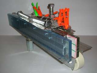
It also is very suitable for making a stable design. It may look like this:
(for this example it is fed by a CD-disc electrostatic machine)
Generally it seems that laser likes sharp edged electrodes. And it is very expected since the E/p ratio is below optimum.
- Electrodes refurbishing.
The electrodes having been broken during making (scratched by filer), the anodized ones, the ones burned by sparks, and simply
old dirty ones may be brought to life by grinding on a fine grit sandpaper with further polishing with a polishing paste on a felt
disc (usig a drill - not by hands of course). However such a rude polishing gives not uniform discharge along the electrodes and
the output will be weaker. One may process the electrodes better - by fine milling with following grinding and polishing on a flat
glass plate... But it is not for home experiments.
- The gap between the wings.
The principles of this laser are far more complicated than one might thought. Particularly it uses the so called 'sliding' discharge
to preionize the main laser volume. (And the experiments with low pressure nitrogen lasers prove that profoundly.)
For the laser to operate smoothly this sliging discharge is needed to be strong enough to provide sufficient amount of UV radiation
to peionize the main gap. But it should be kept weak enough for not to pass the sufficient part of pumping electric current.
With the laser described here it can be achieved when the gap between wings is about 3 mm. When scaling the laser (especially when
changing feeding voltage) one should try to optimize the width of this gap too.
- Scaling.
Scaling of this laser is a real pain in the pass. Generally the laser is very friendly to voltage rising. And even small lasers when being
fed by 30+ kv, produce output comparable to one from low pressure nitrogen lasers. So feel free to rise voltage and dielectric
thickness until You can hold it up (keep it from breakdowns and flashovers). At above 10 kV You will definitely forget the polyethylene and stick to mylar (polyester). Near 20 kv and above the thin electrodes start to be suboptimal. At high voltages better results one can obtain with cylindrical electrodes. Use aluminium pipes ~10 mm in diameter. The main (laser) gap does also grow with rising the voltage. In the best case it will go linearly with voltage. Otherwise it may increase too slow. It may look like You are increasing the gap in the driving discharger from 8 to 15 mm and the main laser gap grows only from 3 to 4 mm. It means that You are low on preionization. There are several techniques to fight this. In the simpliest case You can shorten the feeding pulse and sharpen its front. Use a rail-type spark gap to do this. It really helps.
The laser appears to be workable with length of electrodes in range between ~7 cm and ~30 cm.
Serious efforts directed to build up the travelling wave mode of operation allow to succeed in building 1 meter long laser.
(The required electrode alignment angle gives inter electrode spacing at about ~3..4 mm near the output end. In its order this
requires feed voltages over 25 kv. You will need strong dielectric and face severe problems with avoiding flashovers.)
The output power rises almost linearly with length of the laser and with its supply voltage.
The wings span should be at least enough to provide the energy, necessary for the laser to reach threshold. (Usually
it is ~3 cm per wing, but as it was mentioned above some lasers can operate without wings at all.) There also is a saturation
when the wings span is increased. When it is over ~10cm per wing the discharge time becomes slow enough to for not to feed the laser
and the output stops to increase. When it is over ~20cm per wing You can hit the area of thermal instability of the
volumetic discharge. In this case laser wil tend to show sparks and its output will decrease with further wings enlargement.
Dielectric thickness. The laser requires a certain energy to be put in gas to become superradiant. The energy input
density can be estimated as CEdU, where C - wing capacity, E - electric field tension over the main laser discharge, dU - is the overvoltage that can be achieved along the time taken by the discharge to overlap the laser channel. The capacity is reversely proportional to the
dielectric thickness. E - is almost constant and equal to 3 kv per each mm. And the dU is proportional to the discharge overlap time (read this as 'proportonal to the laser gap or to the charging voltage') So when varying the thickness adjust the supply voltage accordingly (proprtional to the thickness change. Keep in mind however, that too low voltage would not allow You to obtain the volumetic discharge in
a reasonably wide gaps. (And too narrow gaps will make laser inoperational due to diffraction losses.)
On the other hand the laser feels friendly to voltage increasement. Its output rises as U^2 or maybe even U^3. The bad thing here is that (as it was said above) the electrodes are responsible for all. And the rule that larger laser with higher voltage will provide higher output is been obeyed only in general. In any particular case it may happen that larger laser will give less output than its lesser brother. And it bugs seriously.
- Commercial capacitors.
Its sad, but ALL commercial capacitors are too slow. Even low pressure nitrogennies can utilize only a stacks of low capacity
ones (like 470pf or 550pf doorknobs). Some messages about working TEA nirogen lasers using commercial (doorknob) capacitors or Marx bank generators are most probably
related to the ability of the laser to operate on the under-electrode capacity (see above). And those Marxes or capacitor banks
are used only to charge the electrodes fast. The evolution of this idea makes a variant of use for the commercial doorknob capacitors. If You use a charge transfer circuit rather than Blumlein type, then You can use the commercial doorknobs as a storage bank, like here:
The same approach does also allow to use homemade low impedance multilayer capacitors in air pressure air filled
lasers. Unlike the common Blumlein circuit here the inductance is low enough to provide discharge time of a few nanoseconds.
- Variants.
There is a wide area for different designs.
For the first try it has sense to assmble this laser on an iron plate, and to use small magnets instead of weights. (You should
have some after dismantling some DVD-heads for the laser diodes.) This design appears to be portable and endures turns 'over head'
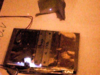
For the compactness one can roll the laser wings. It makes low influence on the laser's operation:
- Scaling.
- Applications.
The laser is interesting for:
- Alignment of long thin things. The UV diffraction divergency is a half of one for the red (He-Ne) rays. Despite the low quality
of its radiation, one can always use a small aperture to 'clean up' the beam. Even then its intensity is enough for the alignment purposes.
- For the pinpoint curing of photo sensitive glues.
- For the dye lasers pumping. (Indeed it's one of the most attractive applications. And the dye lasers are the most entertaining ones.)
- For homemade spectrograph claibration (including ones made of CD-disc and photo camera)
The 337 nm line of this laser is a good (and sometimes crucial) addition to the He-Ne line, obtainable at home.
- There are some messages that the natural width of the line, this laser operates at, is narrow enough to provide
up to 3 cm of coherence length. So this laser may be of some holographic use.
- And just for fun.
The laser is not interesting for
- Drilling, scribing and other material processing (too low output)
<< HOME PAGE
|
|
|


