TEA holeum (mini-guide)
The laser described in a previous guide
has evolved. At almost all by itself. Every reassemblage some part of it was modified.
And in this mini-guide it is described what came out of it.

- Now the laser tube is symmetrical. Cathode and anode modules are identical.
It should be clear that it is tolerant to polarity change.
- Both cathode and anode mounts are equipped with preionizers. (There can not be too
much of preionization. It makes the construction more complex and assemblage more difficult but the result is worth of it)
- Even more preionization is achieved by drilling a chain of holes along the electrodes.
Both cathode and anode are drilled. Now the barrier discharge glows not only
around the perimeter of the electrodes, but also on the free dielectric surface
inside the holes. And it emits light into working laser gap.
- Width of the electrodes is 10 mm for the variant shown here. However such a laser
behaves more soft when increasing width of electrodes, provided that holes are
placed densely. (There is no decreasement of preionization intensity when far
from the electrode edge.)
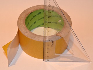
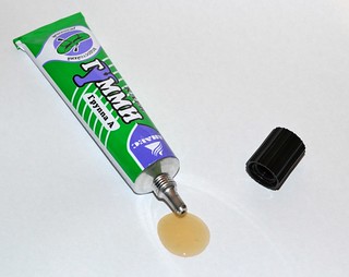
- Instead of double sided sticky tape now a gum glue is used to attach the electrodes
to their places. It improved the reliability and life time of the construct.
- To work with growing pressure the feeding voltage was increased from 10..12 kV
to 20..30 kV. It is clear that type and value of the storage bank were changed.
Now it has 26 capacitors (doorknob K15-4 television type) having 470 pF and 30 kV each.
As the result:
- Top pressure (where laser is still able to lase) was rised up to 600 torr. Without
any helium and with oxygen from air, go figure!
- Output energey on heliumless mixture rised up to 36 mJ per pulse
(however usage of helium does not give as prominent improvement as earlier)
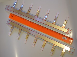
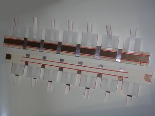
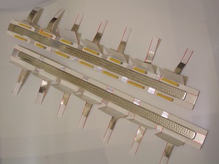
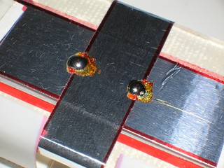
Here are photos of main steps of assemblage of this laser. This one has active
length of electrodes at about 40 cm. One can see that at face side of the
electrodes the holes have 2 mm diameter. And their outlets are properly grinded
and polished (avoid sharp edges). At the back side the holes are chamfered
to have a form of conical caverns. The diameter of cones near their foot
is 6 mm. Those conical caverns when lying above dielectric foil do form a room
for barrier discharge to take place. The barrier discharge provides UV for
preionization.
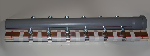
One can also see the conductive belts. (4 for each preionizer and 5 for each
electrode.) Let me remind that without a proper number of contact points
the laser of such a length becomes unstable.
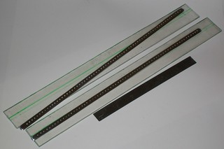
Electrodes. Lemme remind that U can click each image for better quality.
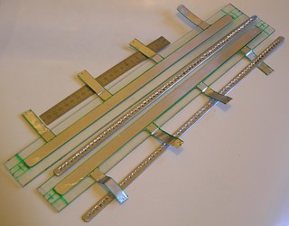
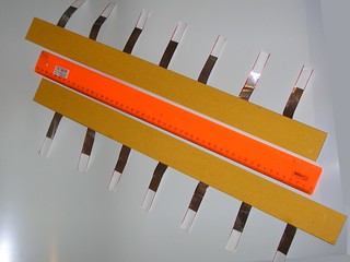
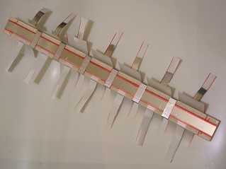
Preionizer foils and back side of the electrodes. One may see the chamfers around holes. Also please note the number of contact 'wings' coming from each preionizer.
Preionizer foils here are covered with double sided sticky tape. Certainly one may put a full layer of the tape, but dielectric is a weak place of the laser, and if it is broken the laser must be disassembled for repairs. And as shown here the sticky tape layer has (air) gaps allowing the sparks (when the voltage is too high) to go around and preserve the dielectric from breakdown.
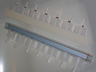
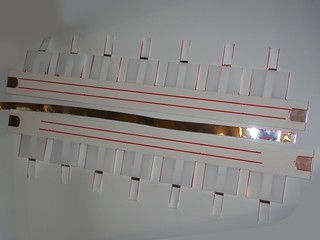
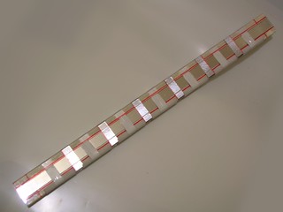
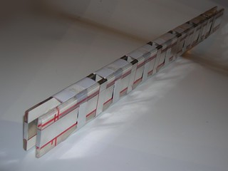
At last the dielectric is mounted. The contact belts (five for each electrode) are clearly seen on the photo. All that remains is to mount the displacement props, to glue the electrodes and to put together the anode and cathode units. This procedure is similar to the one described in the previous guide.
The movie below shows the laser operation.
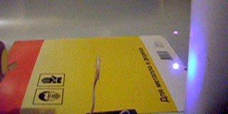
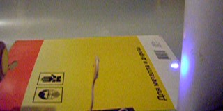
Here I am using a first-surface spherical aluminium mirror (BTW this one is also a car mirror with paint layer having been washed out) to focuse laser beam onto a target. As a target I use some plastic box or a piece of black polyethelene bag. One can see nice blue color of the plume. There are also some sparks directly in the air (not perfect - the air is contaminated by smoke) but it cannot be clearly seen on the video. (In this seria the laser has reached 50 mJ)
Polyethylene bag after the experiments. For the photo it was put onto a piece of white paper and placed over a lamp - to make the damage more clear. The photo is not zoomed do note.
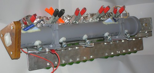
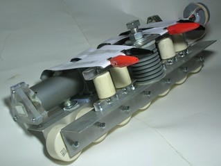
The overview of the laser. Front and back sides. The power supply remains mostly unchanged from the previous variant. Only the voltage was increased and the shunt resistor was replaced by induction coil.
NEW TEA holeum 2
It was supposed that drilled electrodes would allow easy scaling of the laser. In order to check this a sample was build having electrodes width of 20 mm. (Active width scaled 3 times in comparison to the previous version). Here i got a chance to make a detailed photo session of building progress. See the photos below.
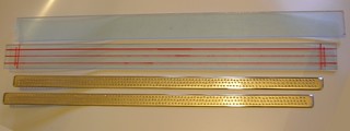
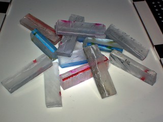
- Electrodes and electrode holders.
- Electrode holders with preionizer blanks.
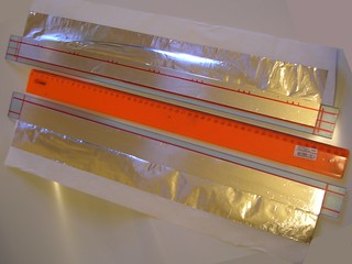
- Marks for proper cutting.
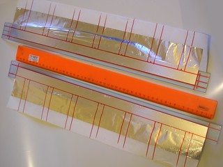
- Electrode holders with complete preionizers. Preionizers are 26 mm wide (yes we still use the discharge over perimeter of the electrodes to make preionization even stronger)
- The same as above covered with double sided sticky tape.
- Mylar sheet (125 mcm thick) has been put over the preionizer. (On the photo You can see face side and back side of the electrode holders)
- The main conductive strip has been just cut from an aluminium duct tape. Its width should be not less than the width of the electrodes.

- The main conductive strip is placed on the back side of the electrode holders. Ends are also used for contact with the electrodes.

- The strip blank for making the conductive belts. (15 mm wide)
- The conductive belts in place. Note the gaps on the face side. They are needed to give free space to the holes.
- The electrodes are now mounted over the electrode holders. A gummy glue was used here.
Use only small drops of the glue - again for not to interfere with the holes.
- Blanks of the spacing props.
- The next stage of the assemblage.
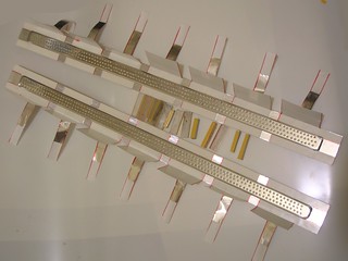
- The spacing props are installed. Note that they are placed between the contact belts of the electrodes and directly over the preionizer contact belts. To secure the spacing props a double sided sticky tape is used.
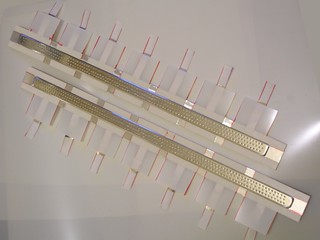
- The electrode holders are placed one over another.
- The other view of the shown above.

- At the next stage a common (narrow) sticky tape was used to secure the electrode holders. Make windings directly over the spacing props places. It reduces electrode bending. Also it is a good idea to solder the contact belts to the main conductive strips. (It reduces arcing and heat dissipation in these places.)
- A common (50 cm long) sewer tube is used as the laser housing:
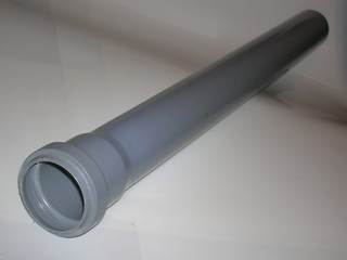
- The tube has 50 mm outer diameter and the electrode holders (42 mm wide) fit it inside well. Do also note that 50 cm long type tube is naturally a bit longer (about 55 cm)
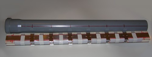
- Here the holes for contact screws are shown.
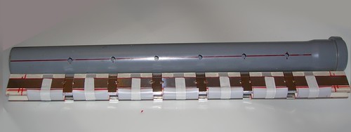
- Note that the contact screws should be placed over the spacing props (the ones between the electrode holders). When You tighten the screws the spacers bear loadings and prevent the electrodes from bending. (Yes this sample is made with a bit of mistake - the screws are between the props and yes they do bend the electrodes. Hopefully You will make it better. Keep in mind, however that the place over the props is already insulated by a sticky tape, so You should make a proper displacement in order to hit the place already not covered with tape but still supported by the props.)
- At last the discharge unit is installed into its housing.

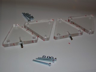
Steps of creating mirror mounts for Laser Tube:
- Four triangle blanks. Two of them are with hoses. Sometimes it is better to place the hoses there rather than to perforate the laser tube.
- Screw the correspondent pairs of blanks and drill the main (central) hole for the beam path.
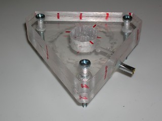
- A good idea is to glue metal nuts into the plastic body of mirror mounts. Use a good epoxy here.
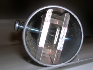
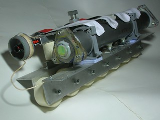
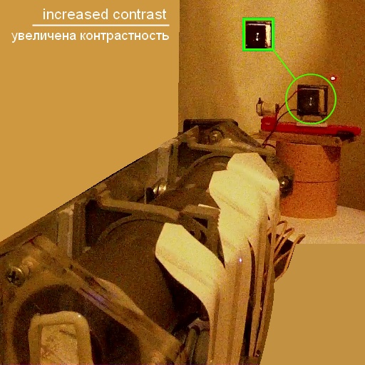
Photo of the complete laser. One can see a new version of the spark gap. It is large, strong and great looking.
The movie below shows the unfocused beam of the laser as seen on the surface of the peltier calorimeter. Note that its surface is common graphite rather than a kind of "visualiser". The spot on the graphite is pretty bright and corresponds to the electrodes width well. So it is clear that the discharge does gracefully follow the width of the electrodes without any kind of contraction.

Also it should be mentioned that so wide electrodes do not require profiling to Chang or Rogovsky shape. They may be plane with rounded edges.
Scaling in this construct has almost approached its limits. 20 mm wide electrodes and 26 mm wide preionizers are placed on 42 mm wide electrode holders. It gives (42-26)/2=8 - only 8 mm of free space for insulation. So the system becomes of rather low voltage type. 20 kv is its limit in the best case. Further scaling will definitely require a plastic tube of larger diameter for its housing. However even this tube is power hungry and when installed on the frame with 15 pcs K15-4 4700 pf 12kv capacitors (the most powerfill laser frame that I have built - the "beast" frame) it is still underloaded.
Spark in the air
 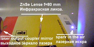
Laser spark in the air is one of the most spectacular phenomena that one can obtain using a TEA laser. It appears when electric field of electromagnetic wave of the laser beam becomes so strong that causes breakdown of the air. However there was no success in obtaining it using only household materials. The problem is that You need here not only high power, but also You need sharp focus. The cleaned from paint car rear view mirror gives too large focal spot due to the aberrations. So a zinc selenide lense from a laser engraver is used here. Moreover, the laser beam itself lacks quality when beeing spawned between aluminium covered car mirrors. So it required the resonator to be made of real laser mirrors. The rear one is completely recflecting and the front one has 50% reflectance. Both are plano. Only after these modifications it appeared to be possible to obtain the optical breakdown of the air.
Judjing by the calculated focal spot size and by the needed intensity (1e10 W/sq.cm) the laser gives at least megawatt of output powe. Most probably - several of megawatts. Energy yield was above 200 mJ by Peltier calorimeter readings. The gas mixture was combustor:CO2 = 1:1. Pressure was 300 torr. The tube (the one with 20 mm wide electrodes was feeded from 70 nf baterry, charged to a voltage corresponding to 6 mm of spark between spheres in the air. (It is about 18 kV, and, yes, it is an overstress for the poor 12 kv k15-4 doorknobs. One of them was broken, but after the replacement all other perform well at this voltage.)
A pair of words on the efficiency.
The last described TEA laser has a fair efficiency - at about 4%.
The energy stored in the capacitors is W=(CU^2)/2, capacity of the bank is 70 nF, and the charging voltage will be 15..18 kV, when the spark gap is set to 6 mm between its electrodes. (It's hard to give more precise values, because measurement of voltage by the spark length is a rough method, and simple kilovoltmeter may lie even worse - due to leaks and corona). Let's take an average U=(15+18)/2=16.5 kV, and then
W=(7e-8*16500^2)/2=9.5J.
Laser output was (as we remember) near 200 mJ.
Dividing of one by another gives eff=100*Wlas/W=100*0.2/9.5=2.1%
Where's the promised four percents?
IMHO now every user got used to the fact that a new 32Gb flash card has free space of 28 trillions of bytes or even less. And every distibuter tends to advertise higher parameters of their products than they are in reality. In one case it is done by exploiting that 1000 bytes is less than 1024 bytes, in other cases - by exploiting differences between lumens and watts, or even by proclaiming peak power as being the characteristic of the device (does anyone remember the famous 'PMPO' system of measure, when little loud speakers were marked as "200 Watts"?)
The same situation is with lasers too. Wanna know how to leech the efficiency? - Watch carefully to my manipulations. A fortiori that this approach is (ab)used in most scientific papers.
The first fact that we need to pay attention to, is that not the whole stored in capacitor energy is inputted to the plasma. And why on the Earth we should calculate wastes of the lossy power supply, when attempting to evaluate the efficiency of the laser only. Lets assume that somesmartbody can elaborate a power supply that can deliver its power into the plasma without any losses. (Actually this statement can be wrong, and moreover it IS wrong, but further we will act as if it was true.)
So the energy of outcoming laser radiation we should divide by the electric energy absorbed by the gas discharge. The least is to measure this absorbed energy. To do it we need to measure the discharge current Id and voltage fall Ud over the discharge. Then we should integrate the Ud*Id product by the time.
Its disappointing but when we try to DIY this procedure, we most probably fail. We shall need to include a current measurement resistor (shunt resistor) into the discharge circuit, and after that all the circuit will change. Its inductivity will rise and cause the contraction of the discharge in the tube. And we really don't want to measure the energy input to the bright spark rather than into volumetic discharge.
Hereby we will try to be satisfied with naked calculations. It is handy that the voltage fall over the gas discharge is constant and depends only to the gap value and mixture contents. So we can take out the Ud from the integral. And the remnant part of it (the current integrated over time) will be nothingh else than the electric charge went trough the plasma. This charge is equal to q=C*(U-Ud). Where U=16.5 kV - is the starting voltage on the capacitors. Ud - is the sustaining voltage of the discharge (the one is contant over time and depends only to the pressure and mixture contents). It is quite expectable that when voltage on the capacitors goes below Ud the discharge will extinct or either contract into a spark. In the first case the further energy input will go only to blocking resistors and should not be taken into account. And in the second case the energy input into the bright arc is also useless from the point of view of the laser action. So we should neglect this value too.
I.e. energy input into the gas is the product of the discharge sustaining voltage with the charge that went through the plasma: W=q*Ud=C*(U-Ud)*Ud.
C is known, U is known, and the thing left is the Ud. For the common reasons they don't like to deal with air - carbon dioxide mixures, so a handbook will be of little use here. But we can estimate this value ourselves. Let me remind that
- discharge sustaining voltage in a gas is close to the breakdown voltage in the same gas in a uniform field. (There exist opinion that both voltages are the same and the opinion that those are different values. But even in case they are different the difference is not higher than several percents, an we will not be interested in such a little correction.)
- The breakdown voltage in gas mixtures with the electronegative gases is mostly defined by those gases. I.e. dilution of the air by carbon dioxide should not affect the breakdown voltage considerably. (You could already observe this when testing the laser tube. The breakdown voltage is similar when it is filled by clear air and when it is filled by laser mixture. Of course I mean helium free mixtures.)
I.e. we'll take that Ud is equal to the breakdown voltage for the 6 mm of air gap (equal to distance between the electrodes in the laser cell) in uniform field at working pressure.
Ud=30[kV/cm*bar]*0.6[cm]*300[torr]/760[torr/bar]=7.1 kV.
300 torr is the operating pressure of the laser. It could be higher, but in this case it would require to charge the capacitor to higher voltage, and the poor k15-4's are already overloaded.
Here the energy input into plasma is: W=q*Ud=C*(U-Ud)*Ud=7e-8*(16500-7100)*7100=4.6J
and the efficiency is eff=100%*0.2/4.6 ~ 4%.
Thats all the stunt. Street magic, isn't it?
Most commercial and industrial CO2-s have efficiency of about 10%. Here we have only two with a half times less. In principle it is possible to squeeze the lost double, by proper cleaning the gas mixture (gas mask for the laser - sounds good) and by using more optimal resonator. But the efforts may appear to be not worth of the result.
Notes on the gas mixture.
Both lasers having been described here were made rather long (active discharge zone length of 40 cm and 50 cm). This was done because in earlier variants of the laser there were problems with lack of gain especially when working near atmospheric pressure with heluim containing mixtures.
Unlike the shorter variants the lasers described here are capable to operate with mixtures with "combustor" - air, where oxygen was consumed by burning, say, isopropyl alcohol. Mixtures having CO2 to combustor ratios like 2:1 or 1:1 are the best. However the lasers can operate even at 1:3 ratio - it gives long pulse that is usefull for, say, drilling.
Both lasers were tested at atmospheric pressure with mixture carbon dioxide:combustor:helium = 1:1:6. (Such a mixture can be obtained as follows: Fill the car tyre with the combustor. Then allow to leak untull there remains only a half of tyre volume. Then fill the tyre with CO2 - luckily the Crossman's 12 gram cartridges have the amount of gas almost exactly equal to fill half of the tyre. Pour a half of tyre content to atmosphere. Then fill it up to full volume with helium from a party balloon. You have 1:1:2 mixture now. Again discard a half of tyre content and fill to fullness with helium. Then You will end with 1:1:6 mixture.) With 1:1:6 mixture at atmospheric pressure both lasers work well. And one can see that they will operate with less helium, however they weren't tested at atmospheric pressure with other mixtures.
Helium mixtures have a pair of drawbacks: a) they degrade rather fast when gas flow is stopped (in 100..1000 pulses output energy drops twice) and b) even a little quantities of air (e.g. the air that came into hoses during disconnecting from vacuum system) cause serious drop of output energy.
To improve quality of UV preionization one can add easily ionizing addition to mixtures. For example one can put a few drops of xylene into tyre before filling. The xylene is available as a paint solvent in hardware stores. Addition of xylene allows to rise the pressure in laser by ~20% without hitting the discharge instabilities. The improvement of discharge stability, working pressure and output energy was observed in all kinds of mixtures: the ones containing helium, the ones without it, the ones with combustor and the ones with common air. In case of usage of xylene with common air it tends to burn out and hence requires gas flow mode. If thre are difficulties with xylene in Your area, You can try toluene (it also can be found in hardware stores) or other aromatic (in chemical sense) solvents. Best results (as they say in scientific papers) can be obtained with organic amines, but You don't want to be chased by DEA, do You? Fortunately there exists one more variant. The additives for automotive fuels intended for octane factor increasement are mostly based upon substances that have low ionization potential. However most of them are cheap and contain isopropanol or the described above xylene. But if You are lucky enough to buy a serious thing, You may rely that You have a good additive to Your gas mixture to get stable and uniform volumetic discharge.
Athmosphere has bin hit!
At last a success in bringing to work a TEA laser at clear athmospheric pressure (1000 mbar, 1 bar, 760 torr...) without any vacuum or helium or pure nitrogen or even a 'combustor' gas. Only air and carbon dioxide from an airgun cartridge.
The design is generally the same as in the lasers above (drilled electrodes with barrier discharge preionization). If one tries to directly go to the athmospheric pressure with this construction, he increases the feeding voltage and hits the dielectric breakdown. If one tries to increase thickness of dielectric it fails because the intensity of barrier discharge drops down and hence preionization becomes too low. The more or less straightforward way of decreasing the spacing between the electrodes is not trivial because of the diffraction losses of the laser beam in too narrow channel. However exatly this last way brought a success.
If we remember that the electrodes are two big and shiny planes, we can try to confine the laser beam in the waveguide between them and hereby to prevent the evil diffraction losses. One may think that the holes will make the waveguide far from being perfect. And it was only for experiment to say whether this system would work or no. And it does.
- A new holed TEA laser was made.
- Length of the electrodes 340 mm.
- Spacing between the electrodes 3 mm
- Overall 'mirror-to-mirror' length 390 mm
- Width of the electrodes 15 mm.
Holes are 1 mm in diameter places as a hexagonal grid with a step of 2.5 mm (it was a handmade drilling so she grid is not very uniform and it still works)
Mirrors are: washed out aluminium car mirror and 85% output coupler (one could definitely use a drilled aluminium mirror with geometric transparency below 15%)
Feeding circuit was a low inductance frame with 7 pcs of high voltage murata doorknob capacitors 2000pf x 40 kv each. (The design of the frame is quite similar to the one used in lasers having been described above).
Threshold voltage corresponds to 9 mm spacing in the spark gap. At 10 mm (26 kv) laser yields 22 mJ per pulse at rep rate of 5 Hz. May be this is not that spectacular as a previous laser was, but it works. "Mission Complete" - air pressure TEA laser on the air with carbon dioxide mixture has been created.
It does not require vacuum pump or nitrogen or helium. However I wouldn't recommend it as 'my first CO2 laser' construction. It requires rather precize assemblage and a bit of knowing what are You doing. One'd better get some experience with reduced pressure systems (look above) before trying to construct this one and putting it into operation.
<< HOME PAGE |